


TECHNICAL SUPPORT


Published 2026-05-21
This tweet is a detailed explanation of the core mechanism of the steering gear drive. It also comes with clearly analyzed real-life pictures and a collection of videos that can be found at any time. It is specially provided for reference by learners in mechanical and electronic control.
1. Question: What is the core underlying mechanism of steering gear drive?
Answer: The key is that the pulse width modulation signal accurately controls the rotation, and drives the rudder surface feedback closed loop through the internal potentiometer, so that the turning angle does not deviate from the preset position at all.
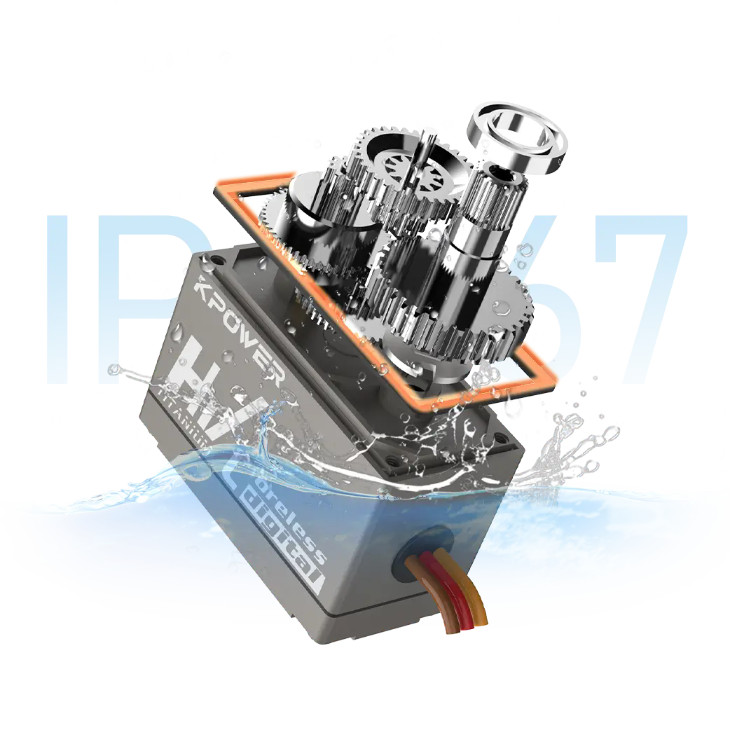
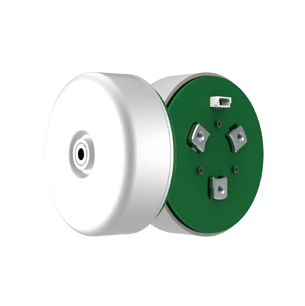
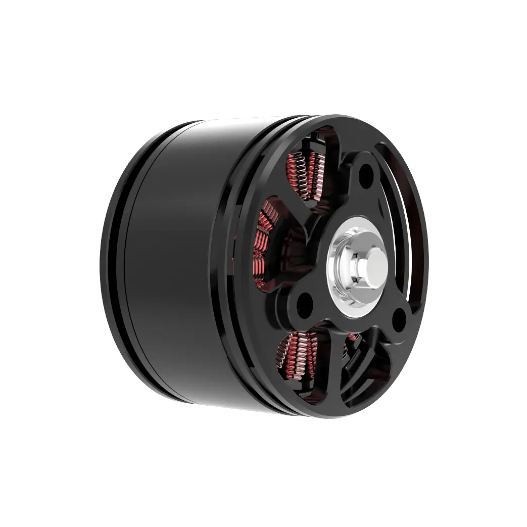
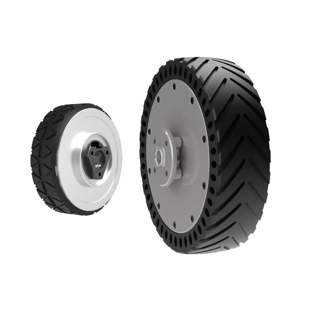
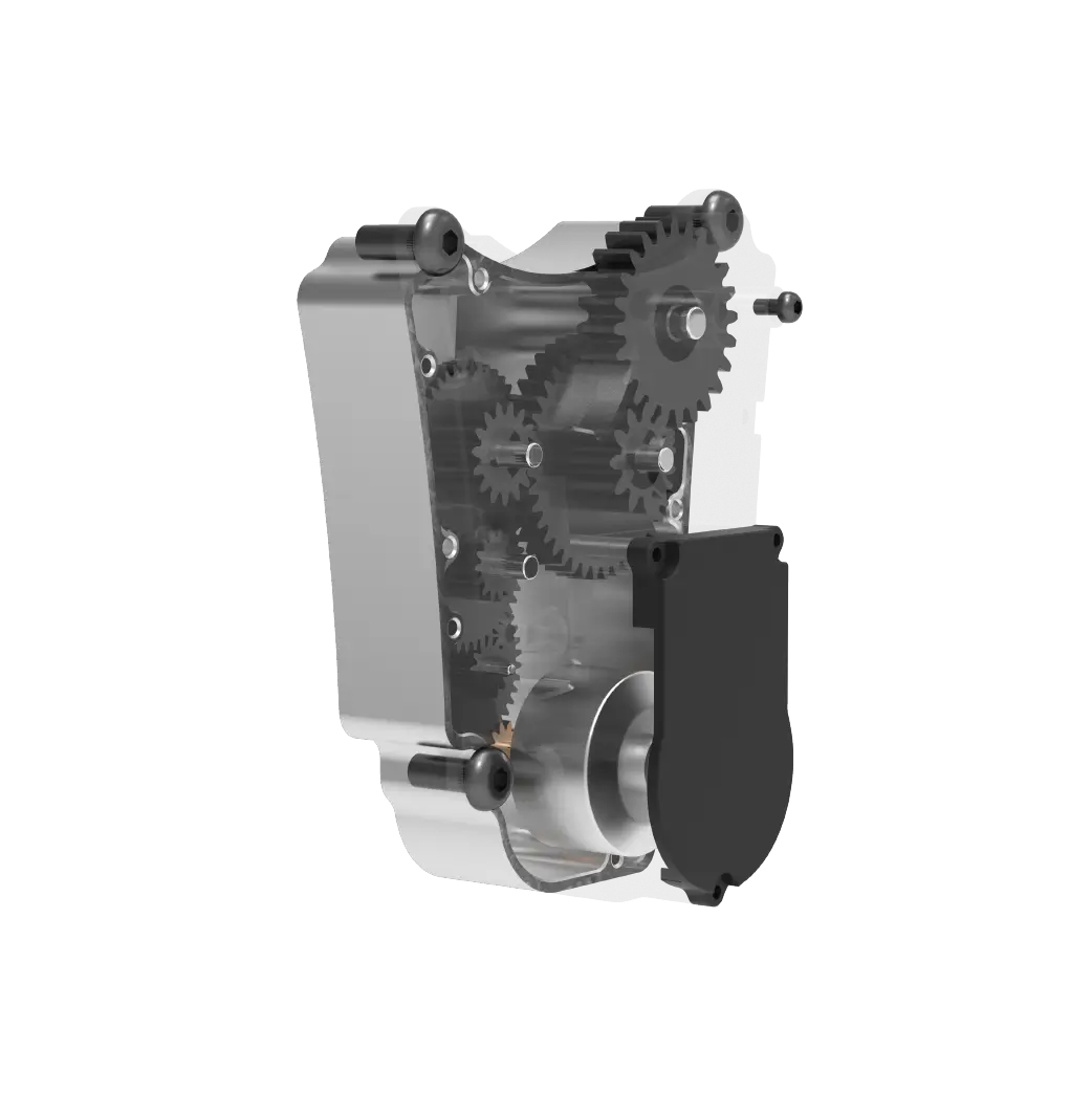
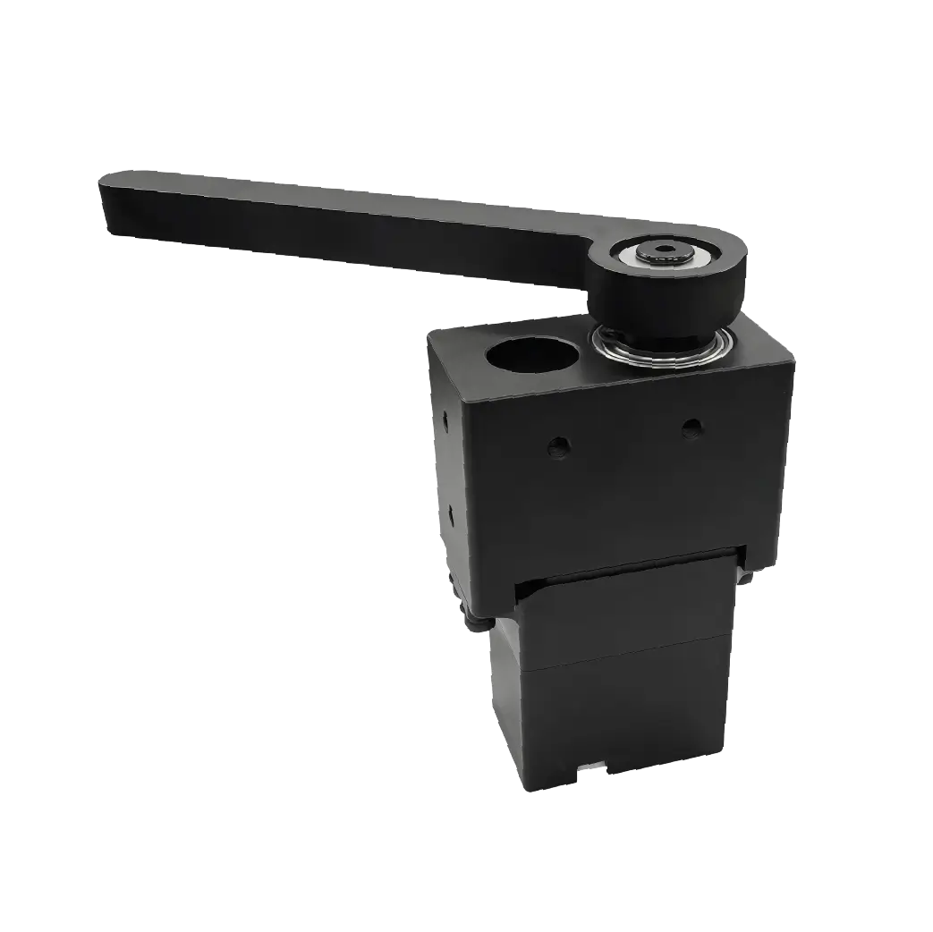
As the core component of the circuit, the pulse width modulation unit uses crystal oscillator frequency division to stabilize the time base frequency and allocates start and stop duty cycles based on the millisecond difference in input pulse width. The pulse width will be subtly adjusted within 2 milliseconds for each degree of rotation. The internal reduction gear set uses a frosted surface inlaid with granular metal, which increases the torque transmitted to the output shaft by more than twenty times. It is paired with a hollow cup micromotor to achieve instant start and stop with timely feedback without delay. In the past, for open-loop motor types without closed-loop control, the drift deviation value of the rotational speed exceeded the range of more than 10%. However, now the steering gear fixes the position through the closed-loop negative feedback loop, and the hysteresis accuracy in the static state is reduced to a range of a few tenths of a degree.

Comparing it with the rough and spacious state of ordinary DC motor speed regulation, there is an obvious difference. Ordinary speed regulation only relies on the duty cycle to roughly control the rotation speed. The control of the position and attitude completely relies on the external encoder for additional calculation and control after calculation. The system is redundant and complicated. However, theservorelies on the native integrated feedback mechanism to eliminate the need for external multiple sampling settings. The process of control volume is clear, simple and clear.
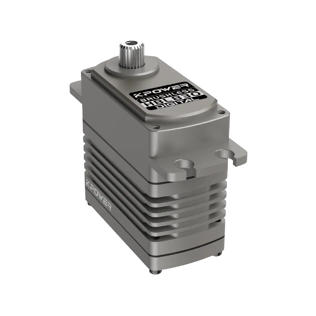
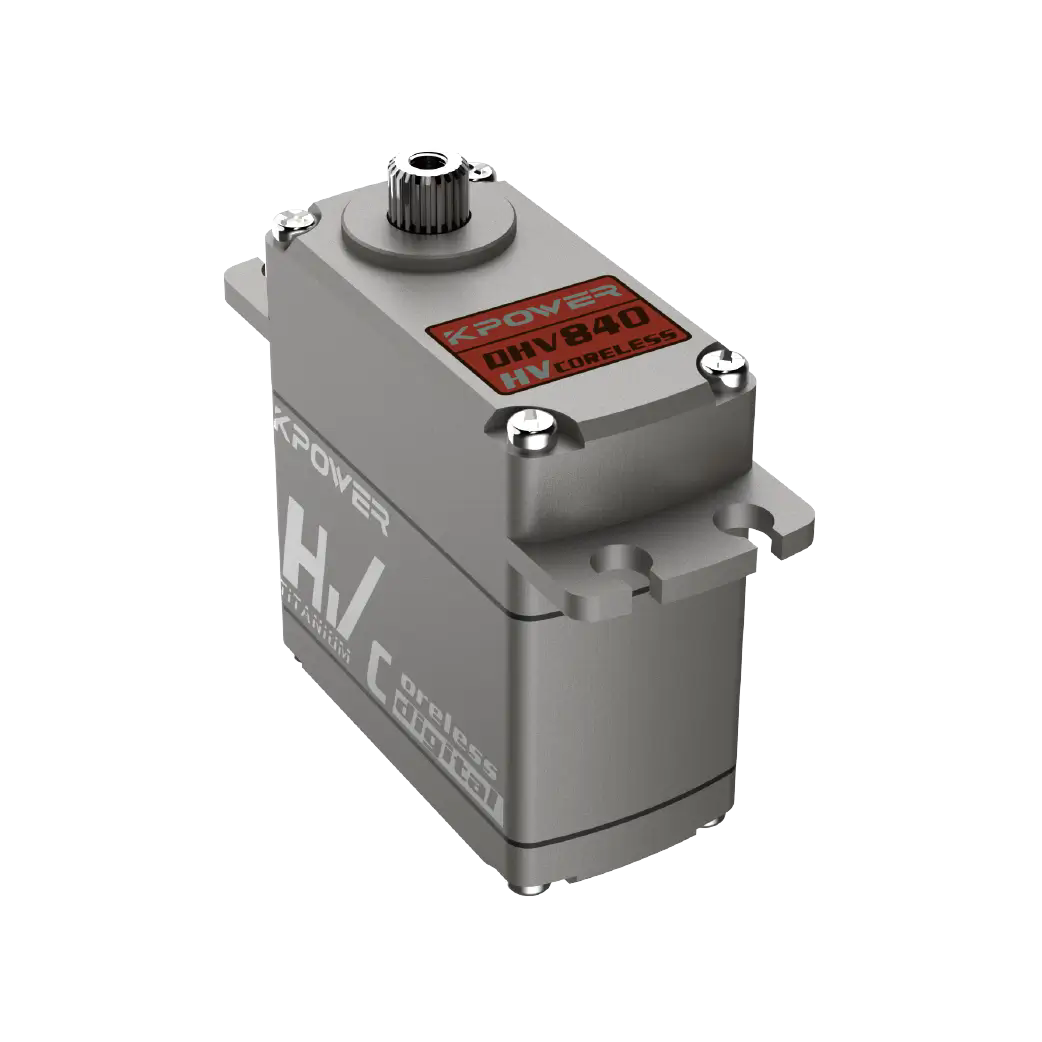
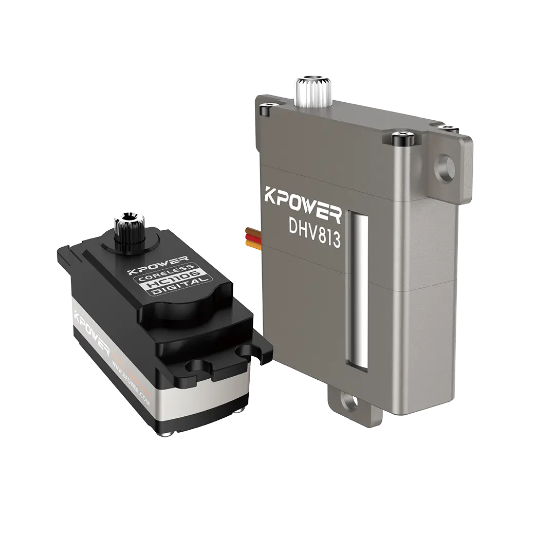
Most novice craftsmen who make remote-controlled boat models have this realization. When they first made a racing speedboat and modified the rudder and chose a conventional analog gimbal, the initial rudder response was slow and the steering lag was half a second, which often caused the driver to run off the track during straight-line racing. After that, he adjusted the median pulse width point by point to the golden value of exactly 2 milliseconds according to the pulse width calibration method taught in the diagram. He immediately saw the steering follow the hand instantly, and his competitive ranking suddenly improved by fifteen levels. This is the role of personally proving the driving mechanism in actual practice. As for the core content covered in thisvideo collection of illustrations ofservodrive principles, it includes more than a hundred real-life disassembly and wiring videos, and more than two hundred full-color vectorized cross-sectional engineering drawings. These contents cover a full range of architectural diagrams from basic analogservos to new era brushless digital servos.
2. Question: What is the core selection logic of the servo adapter driver board for beginners?
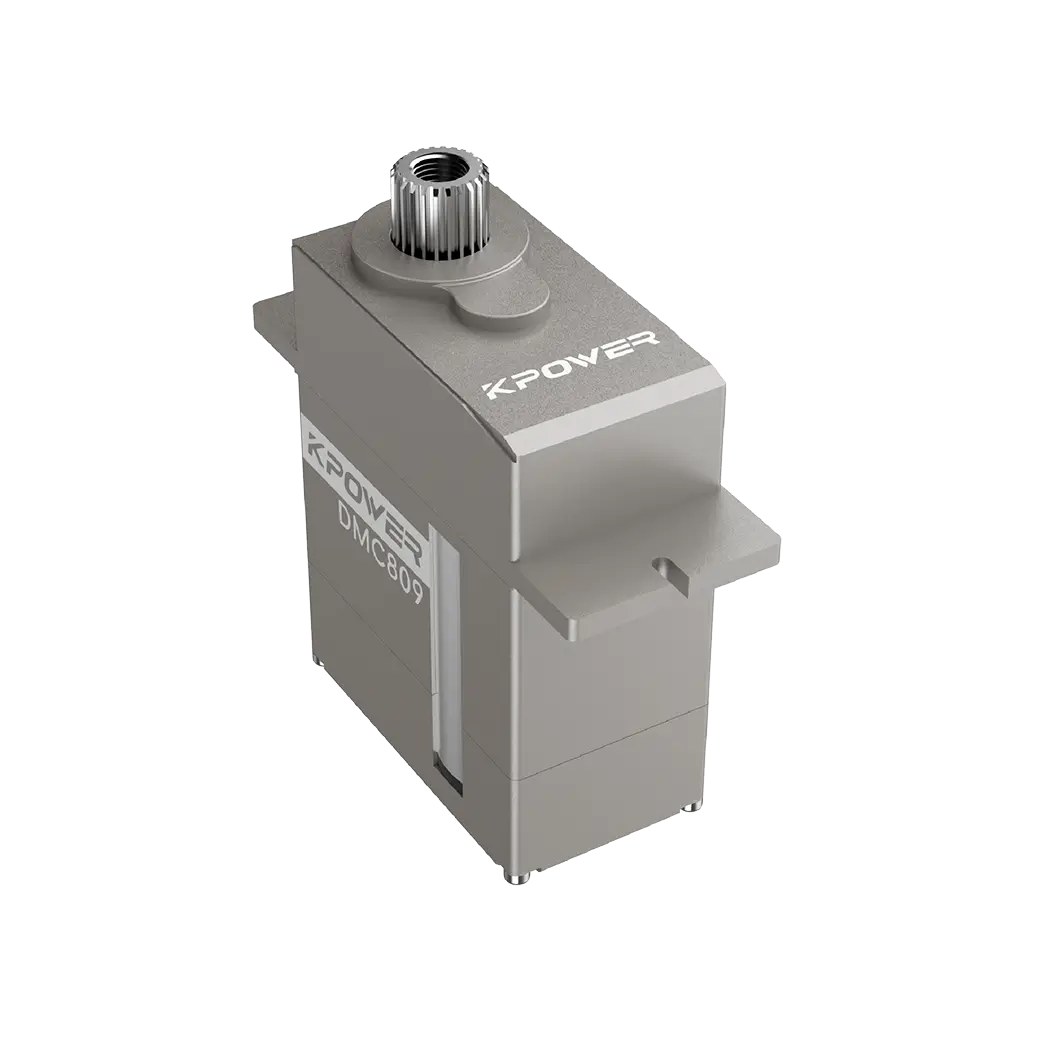
Answer: First, let the signal end match the controller output impedance. You need to find an adaptation numerically, and the adaptation must come first. At the same time, the voltage must be strictly aligned with the calibration range of the servo nameplate. This is to avoid ablation.
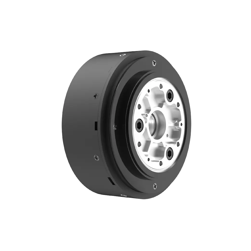
Professionals engaged in the field of electronic electronic control know that when the voltage deviation of the excitation end of the servo is greater than 2 volts, the internal limit will be triggered, and the copper bushing will be worn. If you want to extend its service life, you must first check the level of the PWM signal buffer chip power supply rail during the selection stage. After converting and raising the main level to the appropriate amplitude, connect the servo signal pin. For example, when the college electrical equipment racing team used an 8-volt power steering gear in the early days, they rashly connected it to the 5-volt control board with a signal line. As a result, the digital motion was lost and the rudder parts were burned out repeatedly. After careful review of the tips on resistor-capacitance filtering arrangement in the illustration video, they added a signal path, connected a 1k damping resistor, and conducted an 8-hour continuous pull test. The rudder angle was as stable as a rock throughout the whole process, without any unreasonable drift.
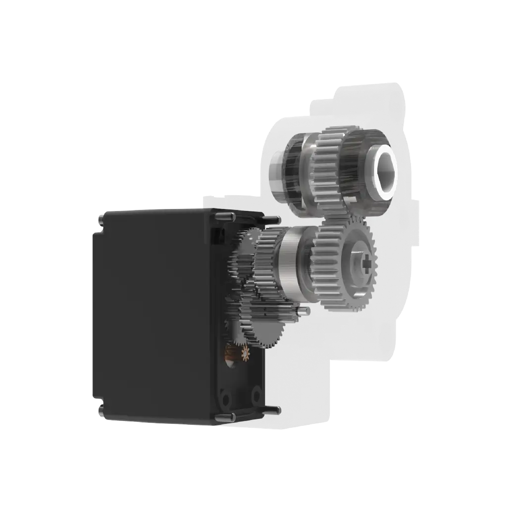
Compared with the complicated mode of traditional DC motors that require external H-bridge discrete components to be driven, the situation is completely different. The servo relies on its own native integrated MOS tube power amplification circuit, eliminating the need to expand the bridge. The entire wiring process is reduced by more than half, and the proportion of the drive PCB board area is reduced by nearly 30%, which largely squeezes out the space of the control board to accommodate other sensing components.
Those of us who have participated in the study of robot competitions can clearly review the past scenes of the competition. In the early stages of team formation, a six-legged climbing exoskeleton prototype was built. Six sets of rudders moved at the same time. It was easy for power supply to drop, compaction, and uneven joint movements. Later, I carefully watched the schematic video of the driving mechanism principle and learned the distributed power supply technique. I split the 4A power to each rudder group’s independent power rail and shared the signal bus synchronization control point. In the end, the stability of the six-legged timing sequence was greatly improved. This is an excellent and vivid proof of thoroughly understanding the true meaning of servo drive and obtaining practical operational gains. Today's collection has once again added screen recordings of fault-tolerant protection debugging operations under various typical working conditions. The number reaches more than a hundred segments, which can accurately solve the confusion caused by more than 90% of common operations when learning and practicing.
3. Question: What process should be followed during the servo feedback calibration stage?
Answer: First, disconnect the machine and connect the code, start the no-load zero position pulse width adaptation calibration, and then check the stop point hysteresis error step by step under the load condition, and control it within the range allowed by the indexing.
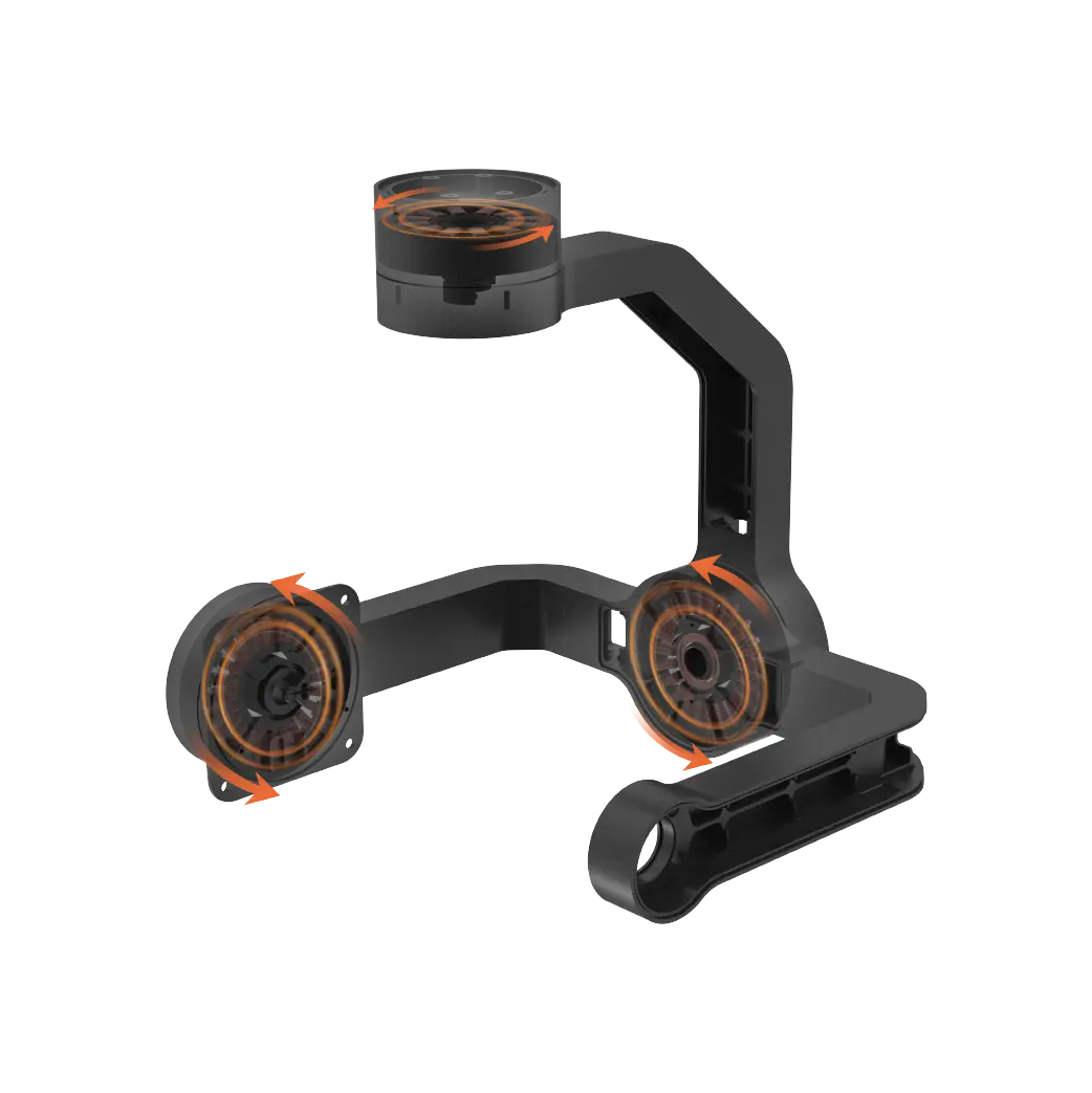
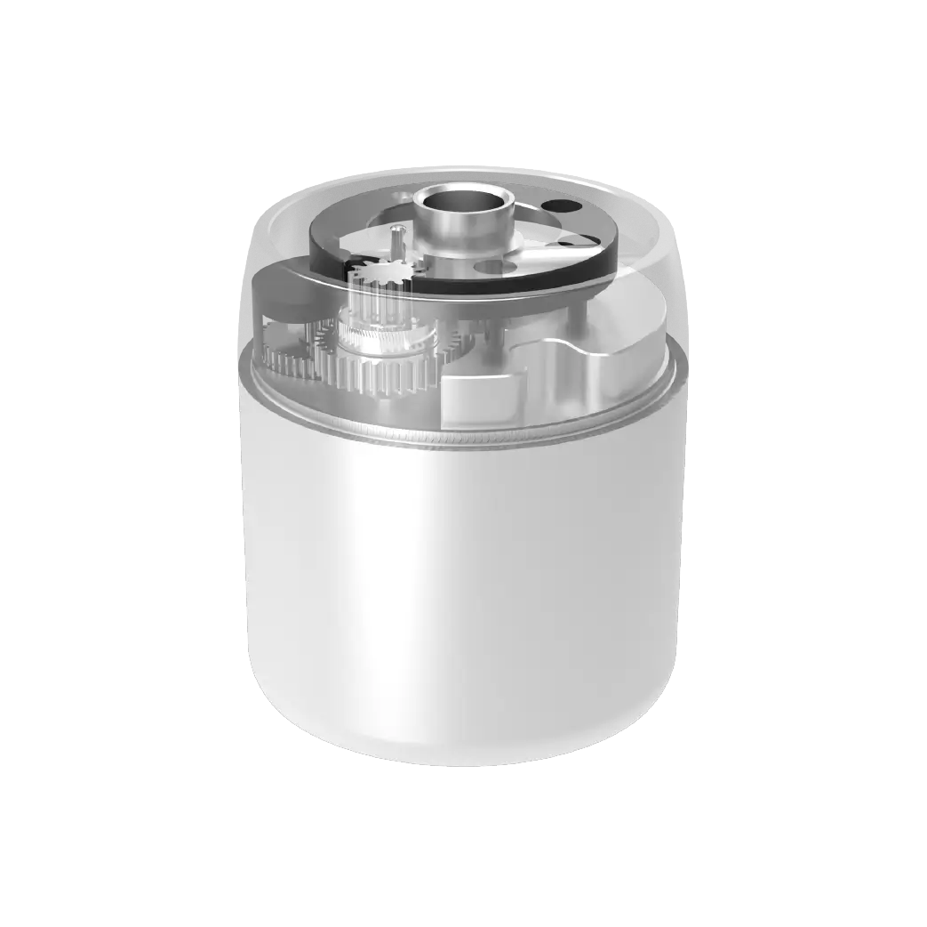
First, the operation of scanning the Shiton no-load pulse width to the zero position is listed as the most important task. Then, with the help of a programmer, the periodic pulse width is gradually adjusted so that the step increment unit is hundreds of nanoseconds. Then the analog-to-digital conversion reading output by the potentiometer is collected. After that, the preset graduation angle and the actual code value are checked one by one. Finally, the device's own bit corresponding number table is calibrated and generated, and stored in the memory block of the MCU. For high-end application conditions, load calibration is performed on the servo and camera shaker, and the position parameters of the shooting action are recorded step by step. This can achieve smooth operation of the shaker without any feeling of sluggishness or frustration. When the training workshop first had a cloud platform for photography and shooting, it did not calibrate the entire pulse angle numerical scale, and the lens always had an uncomfortable feeling of being stuck and pulled when turning. After completing the entire calibration process, the cloud machine operation and shooting image frames rotated completely smoothly and continuously, as silky as a mirror.
Compare this with the unfavorable situation in which the movement deviation can reach 3 to 5 degrees in the open-loop scaleless drive mode. After the completion of the closed-loop step-by-step scale correction mode, the deviation shrinkage can reach an extremely low level within 0.2 degrees. The accuracy of the whole machine's posture control spans a new level, and the texture step-up is very obvious.
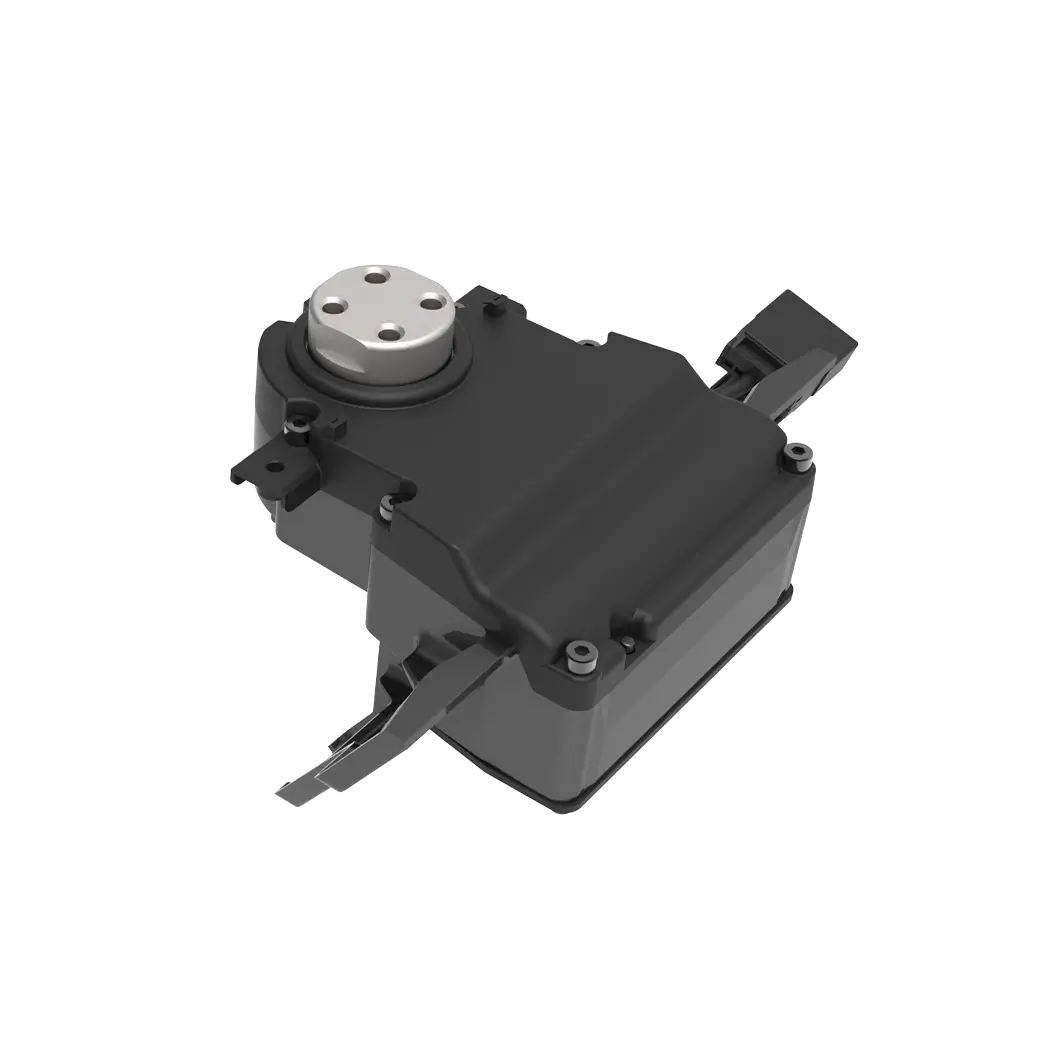
Many researchers who study marine navigation equipment in universities know that the underwater sampling detection carrier controls the depth sounding sample collection arm through the steering gear to locate the collection point, which has an extremely important weight. Initially, when the water was in non-standard working conditions, the buoyancy moment deviation would cause the posture to deviate, and the accuracy rate of the mining points once soared by nearly 20%. Later, I looked back at the driving mechanism correction demonstration video and made a supplementary simulation of the position and attitude difference fitting when the vehicle was fully loaded. After optimization and adjustment, the point hit rate was directly improved to a level that is absolutely superior to international maritime equipment standards. Examples of the application effects of the empirical feedback mechanism like this are all recorded with native real shots in the integrated materialof the steering gear drive principle illustration video. When you learn and watch, you will feel like you are actually there.
This will integrate the whole process of electronic control drive study in the past into the illustrated video system, and learn the energy efficiency of step-by-step practice, which can save at least 70% of the study time compared with scattered fragmented researchers. In the future, intelligent servo drive technology will continue In the iterative and advanced scenario, if you master the essence of the underlying driving logic of the servo, you can freely expand and extend the new landscape of various innovative electronic control formats. You can immediately start reading the book, study it frame by frame, and try it out in practice, so as to gain early access to the gains gained from practical research.
Update Time:2026-05-21
Contact Kpower's product specialist to recommend suitable motor or gearbox for your product.


