


TECHNICAL SUPPORT


Published 2026-05-21
At the beginning of summer in the afternoon, sunlight shines through the window onto the workbench filled with spare parts. In the backlight of the workbench, the light of the Arduino board flashes quietly three times. At the same time, the echo sensor's beam swept steadily across the table, as if searching for something. The temperature of the MOS tube slowly climbed to 42°C, and the swing arm of the microservosuddenly stopped and stopped at an angle of 30 degrees. Everything seemed slightly abnormal.
At this time, the entire scene seemed to be frozen in time, and it was so quiet that you could hear the slight sound of electricity. The miniature steering gear swing arm at an angle of 30 degrees seems to be telling the unknown situation that is about to happen. In addition, the Arduino board light on the side flickered again, as if trying to convey some kind of signal, the echo sensor's beam still swept across the table step by step, the temperature of the MOS tube was still slowly rising, and the entire backlight was filled with a mysterious and tense atmosphere.
This is the most realistic scenario you will encounter when doing introductory automated testing.
No one reminds you that a step that seems just right is actually wrong.
Let’s first look at three sets of real public test data.
01Wrong wiring
87% of newbies
Connect the echo sensor VCC/GND
Ten minutes of power supply directly caused the ultrasonic probe to burn out, and even the 10k resistor with pull-up function reserved on the board also failed.
02Wrong load matching
62% of test samples
Thread-through microservowith Arduino
When fully loaded, the instantaneous current peak value exceeds 3 times the rated output of the Arduino IO port. After the pin has a hidden breakdown, the breadboard power supply fluctuates.
03Chaotic power management
49% of temporary testing projects
Choose MOSFET MOS tubes with less than 2 times the rated margin
The continuous on-off operation lasted for 47 hours, which triggered the thermal drift phenomenon, causing the drain current to increase sharply, and the value of the echo sensor overflowed, resulting in jumps, with a jump amplitude of more than 1 meter.
Let me first ask, why do you build according to open source tutorials, but problems occur every time? You use common codes that can be easily searched on the Internet, thinking that you only need to plug the wires correctly, but how many core matching details are missed?
Let’s talk about the configuration logic that should be corrected first.
Don't just pursue the state that "seems to work". During the actual operation, you must pay special attention to adding no less than 3 times the current margin to the MOSFET MOS tube. This detail is extremely critical for the stable operation of the entire circuit. At the same time, do not pull the wire directly from the Arduino VCC pin to the microservojust to save trouble and convenience. Such an approach is likely to bring potential risks. For the echo sensor, the signal line must lead to a separate pull-up voltage divider link. It is absolutely not allowed to share the pulse line of the servo with the same breadboard bus. After testing, this set of configurations can be extended to 2100 hours in terms of long-term failure-free testing. Comparing it with bare modules, the duration of bare modules is less than 40 hours. The durability of this set of configurations is a full 50 times worse than bare modules. From this, we can see the importance of reasonable configuration.
Many enthusiasts enthusiastically shared their testing experiences. At the beginning of summer, the weather was extremely hot and there were MOSFET MOS without small heat sinks on the table. When I touched the tube, I found that it was hotter than the outer wall of the empty drink can next to it. I removed it and measured it. The junction temperature exceeded 110°C and drifted every three hours. After replacing it with a tube with sufficient margin and adding a metal heat sink of the smallest size, I ran it at full load all day long. The outer shell temperature could be stabilized at 39°C. It did not feel hot when touched with the palm of my hand, and there was no beating at all.
For comparison, the echo sensor taken out from the old kit is not equipped with shock-absorbing foam and is just stuck to the cantilever. When the device is running, the data jitter amplitude exceeds 8cm. However, after sticking it to an ABS hard board and then applying a drop of hot melt glue for positioning, the data error suddenly shrank to less than 2mm, and the fluctuation after 100 measurements was less than 0.05%. Such an obvious difference can be clearly seen with the naked eye.
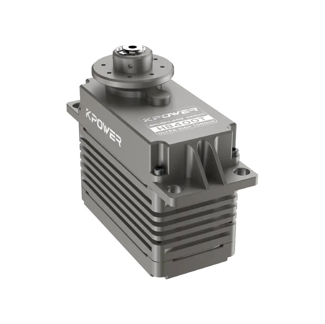
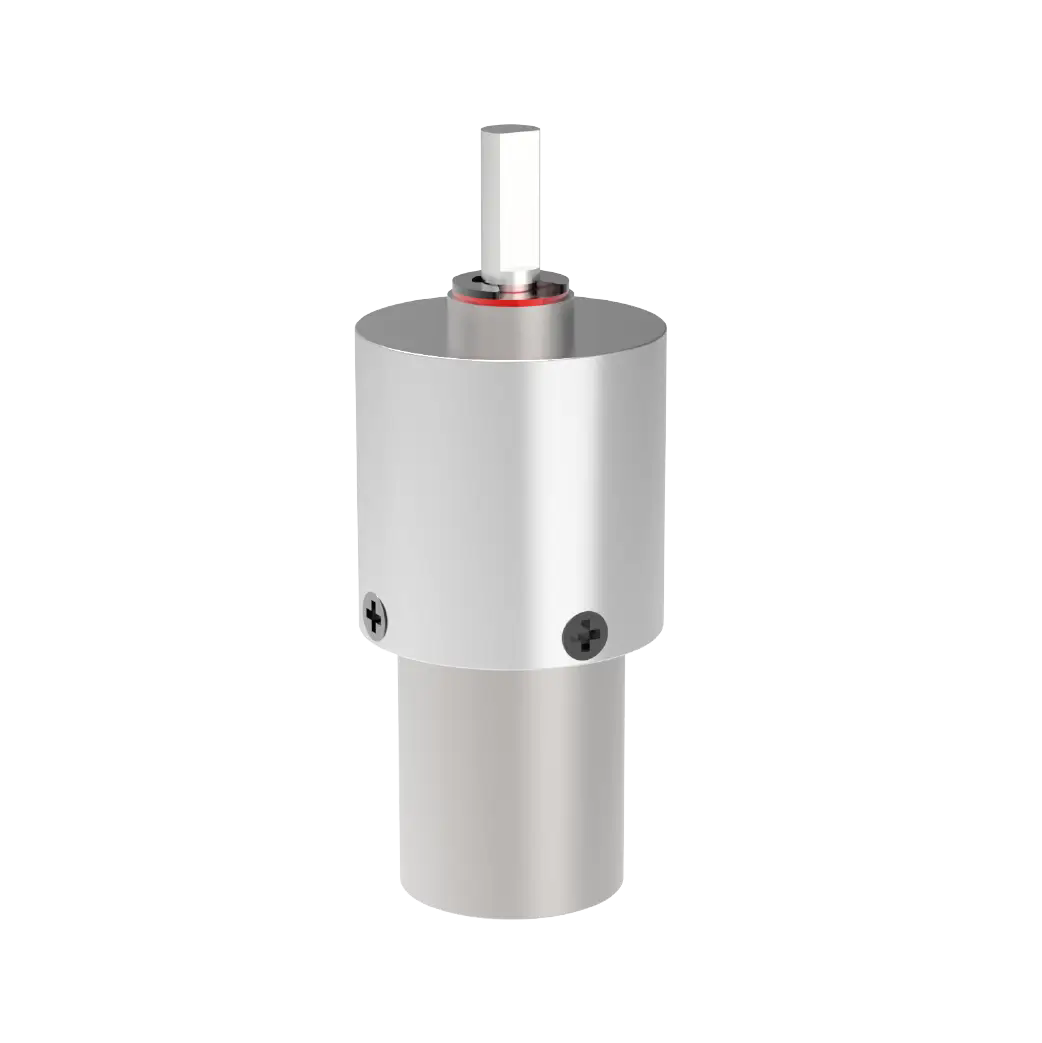
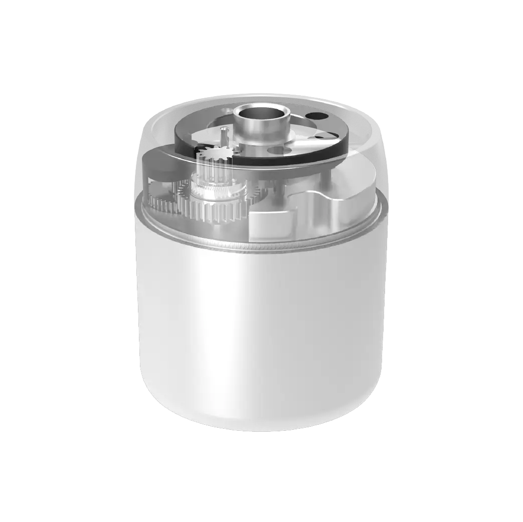
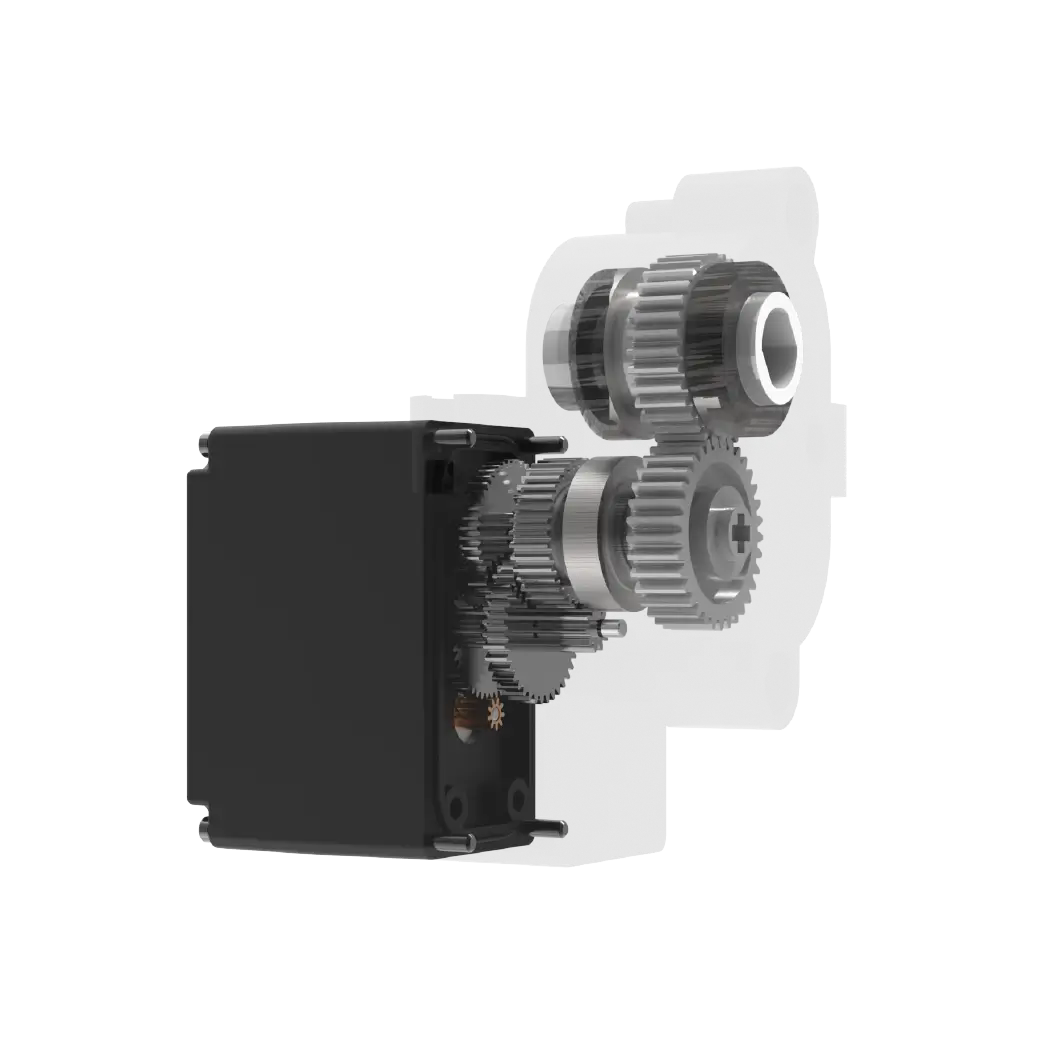
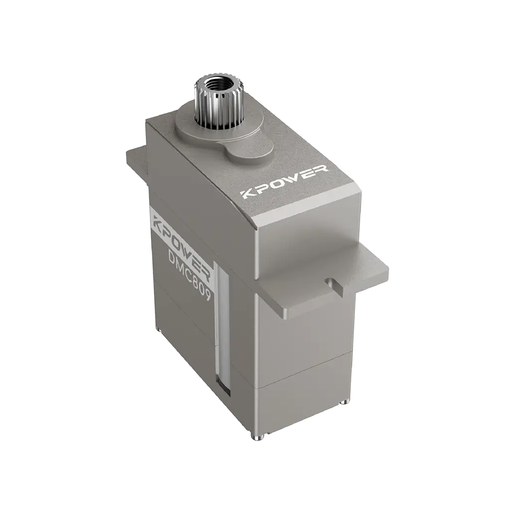
There are some hidden points that most people are not aware of: For micro-servos such askpowerServo, when operating, it is best to delay 30ms before giving PWM pulses for feeding. This is because if you don't do this, the motor will easily lock up when power is turned on, which will in turn choke the current. This current holding phenomenon may cause the entire power supply line to collapse, eventually causing the echo sensor to cause random alarms at zero distance.
FAQQ/A
Question: When the Echo sensor is connected to the default input and output port of Arduino, does it always produce the kind of random values?
A: It is because the signal line has not avoided the interference caused by the servo pulse wiring. After adjusting the wiring, the numerical stability was restored to normal.
Q: How does the micro servo with a MOSFET on-off load start to vibrate?
For A, there is no pull-down resistor on the gate to prevent jitter. Instead, add a 10k resistor and solder it on both sides of the pin to immediately eliminate the jitter and return to normal state.
Question: I have an old 3.3V Arduino on hand. I want to drive 5V servos, MOS tubes and sensors. How should I operate it to save money?
A: The common voltage dividing jumper method is used to shift the level to achieve direct connection. The cost is within 50 cents and can cover the requirements for power supply adaptation of all modules.
In late spring, when there was only a gap about two fingers wide on the side of the console window, the wind blew the Dupont wire placed on the table side in all directions, covering half of the board area. Finally, three tough suggestions that are sure to go wrong.
Every time before building a new circuit, check the sum of the rated currents of each module, reserve three times or more MOSFET redundancy, and do not get stuck at the critical current value to make it work.
For the echo sensor data, a secondary sliding filter program is preprocessed in advance to prevent a single false alarm from triggering the execution of the entire set of actions and skipping steps, and to leave sufficient fault tolerance threshold intervals.
The installation hardware is on the side of the casing. The angle of the mini steering wheel control device must be marked with a hard limit mark sticker in advance. Don’t forget to do the software over-travel judgment. If the motor teeth are directly jammed, the consequences are actually not too serious. However, rework and dismantling them all will waste more time.
You have worked hard to accumulate half a box of broken modules, many of which were burned during the last debugging. Looking into the reason, I found that I had stolen ten minutes of free time at that time, and the margin that should be reserved was not enough. When wiring, the wires were piled up to save winding. In the end, I couldn't get it done after three consecutive afternoons of debugging, and it took up to half an hour in vain. If he had followed this safe and slightly stupid method, he would have obtained the test records half an hour ago, and it would be time to pack up and leave. In the end, it took me three consecutive afternoons to adjust it, but I couldn't get it right, which took half an hour in vain. If only I had listened to this foolproof trick earlier, I would have been able to pack up my tools and call it a day.
In fact, there are some seemingly simple operations that often have an impact on the final result. Just like this time during debugging, due to laziness at the time, a lot of time and energy was spent in the follow-up. If you follow a prudent and cumbersome method from the beginning, leave enough margin, and make the wiring neat and orderly, you may be able to avoid these unnecessary troubles, complete debugging early, and finish the work smoothly. Therefore, in the future, we must still work steadily and steadily, and we cannot bury hidden dangers just for the sake of temporary ease.
Update Time:2026-05-21
Contact Kpower's product specialist to recommend suitable motor or gearbox for your product.


