


TECHNICAL SUPPORT


Published 2026-05-14
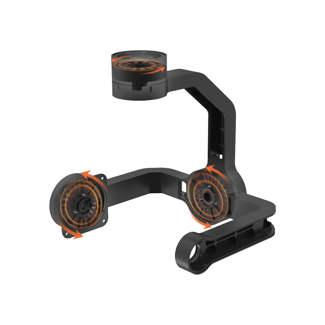
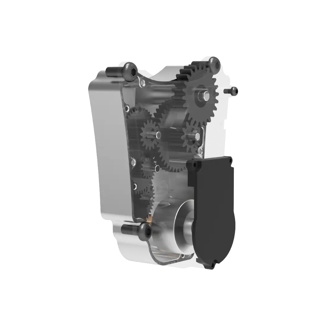
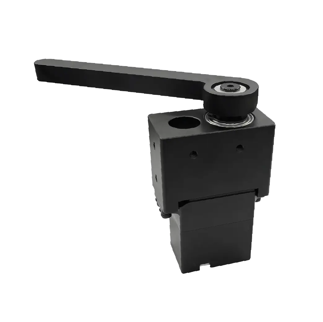
1 Novices will be at a loss when faced with the messysteering gear reversing valve drawings, right?
Don't get angry yet.
Let's first look at the drawing assembly panel spread out on the table.
The basic parameters of rated pressure and flow are marked in the upper left corner of the panel.
This line of parameters is the first level of all selection and adaptation.
In the past, we have encountered many pitfalls in which a novice made a mistake in the rated pressure labeling, causing the entire prototype to burst directly during testing.
It’s only after I walked through it that I realized that the details here cannot be sloppy.
It is often said in the engineering community that "a slight mistake can make a thousand miles".
This is really applicable when checking the details ofthe steering gear reversing valve drawing .
Here, the first step is to sort out all the basic parameters marked on the panel, and no small number can be missed.
All the adjustments required for the subsequent design that you hold in your hand can only be presented on the premise that these numbers do not deviate.
Anchor the parameters and hold this key step tightly to ensure its accuracy. In this way, 90% of your subsequent debugging detours can be directly avoided, which can greatly improve work efficiency and reduce unnecessary trouble and time loss.
Transition to the detailed inspection link of the valve group cross-section view.
2 In the cross-sectional view, the matching tolerance marks of the valve core and valve sleeve can be clearly seen.
This part is the core of whether the entire reversing valve can achieve zero reversal stagnation.
Previously, there was an engineer who had been working in the engineering field for more than three years. When faced with the work task, he did not carefully check the H7/h6 tolerance for valve core matching marked on the drawing. Instead, he relied on his usual daily habits and casually carried out processing operations according to the universal parameters.
In the end, the parts were completely stuck after being pushed and pulled. It took almost three weeks to remove the plating and rework.
The man-hours and materials were directly burned to the tune of tens of thousands.
Professionals who are familiar with the industry know that if the gap difference between the valve core and the valve sleeve is even more than two microns, the internal leakage of the entire valve will directly exceed the standard by more than three times.
On the drawing, you spend ten minutes checking the tolerance numbers. In this way, you can save the energy required to rework dozens of times in the future.
This is so cost-effective that it has no friends, and the old engineers will tell you about it.
If you understand the tolerance marking of the cross-section drawing, the success rate of the core parts produced in your hand will directly increase to a big level.
Transition to the oil port interface size details bar area on the side of the drawing.
In the details column, the thread depths of the four oil ports called P, T, A, and B are clearly marked, and their diameter specifications are also clarified.
Don't think of this as irrelevant side information.
In the previous batch trial production, there was a problem that the thread depth of the entire batch of valve interfaces was 1mm shallow.
When the whole machine was assembled and it was time to connect the external oil pipe, it couldn't be connected directly. It was forced and the sliding teeth were screwed. There are more than 20 pieces of valve housing.
The whole batch of parts almost had to be reported directly, which was painful.
Senior colleagues always say that there is no shortage of every last millimeter in the hydraulic oil circuit.
When it comes to steering gear systems, this sentence applies to the core. You can’t be lazy even half-heartedly.

After getting the drawing, spend three minutes checking the dimensions of the oil ports one by one to eliminate docking pitfalls in advance.
By paying attention to the small details in advance, your cross-scenario adaptation efficiency will increase by at least 30%.
By thoroughly understanding all the markings on the oil port details, the adaptation failure rate of the whole machine can be directly minimized.
Transition to the test case schematic module that comes with the drawing.
4 This part draws all the test boundary conditions of endurance shock and commutation response delay.
Those senior veterans with rich experience are extremely keen to delve into this part of the content, study it to a very thorough level, and understand every detail deeply. They will never act blindly at the beginning, and they will never rush to catch up with the production schedule.
There was a previous project where the team failed to review the drawings and set the 7,000 reversing cycle test requirement.
The structural matching ratio is based on the 3000 times durability of conventional valves.
When it was taken for standard testing, it directly reached 4,000 times. As a result, the valve core became worn and its movement became abnormal. As a result, the entire valve was sent back to the factory for repair and full optimization.
I have been busy with work for nearly a month and am just dragging my feet.
As the old saying goes, "precautions will lead to failure."
When working on a project, you should focus on this part and carry out comprehensive adaptation work in advance, instead of waiting until problems arise in the test to make up for the loopholes. Do you understand?
After getting the drawing, you must first draw the test condition requirement circle in red, and read it twice more. You must also leave an excess of 20% in the range of tolerable errors in performance.
The smoothness of the entire process will be maxed out immediately, so there is no need to panic and put out the fire temporarily.
After thoroughly understanding the schematic diagram of the testing conditions, the passing rate of new products can reach over 90% in one pass.
Transition into the exclusive Q/A session.
Q1 How much tolerance margin should be left on the drawing for the most reliable fit of the valve core?
Let’s talk about the conclusion first. Leave a design margin of two to three microns to take into account the needs of smoothness and leakage suppression.
Q2 If you don’t understand the hidden line annotation of the section, how can you quickly make up the basics?
As long as you look for examples in the GB/T 4457 mechanical drawing specification, you can quickly get started and understand the relevant content in just two weeks. This is the conclusion given directly in the first sentence. In this way, learning efficiency can be greatly improved, allowing learners to quickly grasp the key points of mechanical drawing specifications and lay a solid foundation for subsequent work or study. After this, whether they are professionals engaged in mechanical design, manufacturing and other related industries, or novices who have just come into contact with the field of mechanical drawing, they can use this method to quickly become familiar with and apply the specification and improve their professional capabilities.
Q3 How long does it take to test the reversing valve in the steering gear scenario before the durability reaches the standard?
Let me give a conclusion as the first sentence. According to the conventional requirements of the steering gear, under the condition of full pressure, at least 7500 reversing cycles are required for base preparation, so that the performance will be stable.
Finally, I will throw out a core question to everyone.
In your hand, you are firmly holdingthe drawing of the steering gear reversing valvethat has been gathering dust half a year ago and has not been straightened out until now. At this moment, you are in a state of trouble. You are thinking in your heart, which step should you start from and immediately start to fully understand all the contents of this drawing?
Don't delay.
Now find the drawing on the table that you can easily point to and check the basic parameters in the first step.
Make the first move.
Senior experts who know the ropes well know that you need to pay close attention to the details of drawings and other things. Just spending one minute of concentration to study the drawings carefully will save you ten days of worthless busyness and prevent you from doing a lot of useless things.
It is always a hundred times more effective to get started quickly and achieve results than to just think about it.
Update Time:2026-05-14
Contact Kpower's product specialist to recommend suitable motor or gearbox for your product.


