


TECHNICAL SUPPORT


Published 2026-01-19
Picture this: you are holding the SG90 micro servo that is as small as chocolate and preparing to put it into the latest robot. But here's the problem - either the size of the 3D files in the computer doesn't match, or the position of the axis is deviated, making it a bit awkward to install. You sigh at the screen, thinking how much trouble you would save if you could have a number that closely matched the real thing.
This kind of thing is quite common, right? You might be simulating a robotic arm, or designing a small automation device, or even just want to 3D print a casing. But what you search online often gives you a headache: the holes are misaligned, the gear outline is blurry, or the design of the fixed ears is simply missing. The result? Either it is a waste of time to make repeated modifications, or it is forced to work, only to find interference or friction when it is actually running.
In fact, the solution can be very simple.
Why do we need “accurate” 3D?
Think of it as a preview. A precise one that allows you to test installation methods, movement trajectories and structural fit in virtual space. Just like looking at the blueprint before building a house, you can find out in advance: "Ah, the screws will get stuck here" or "The angle will hit the wall here". For a small servo like the SG90, a dimensional error of even half a millimeter may become a big trouble in actual assembly.
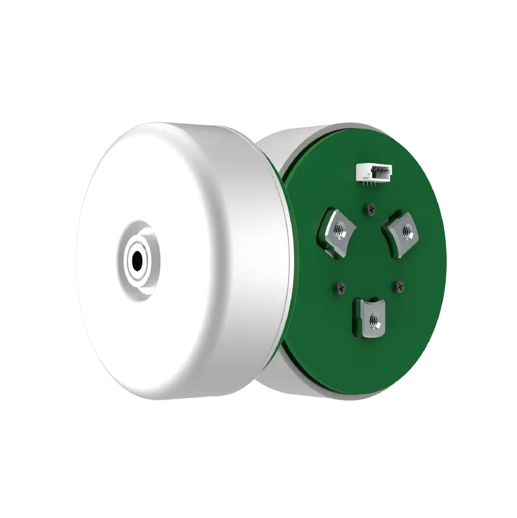
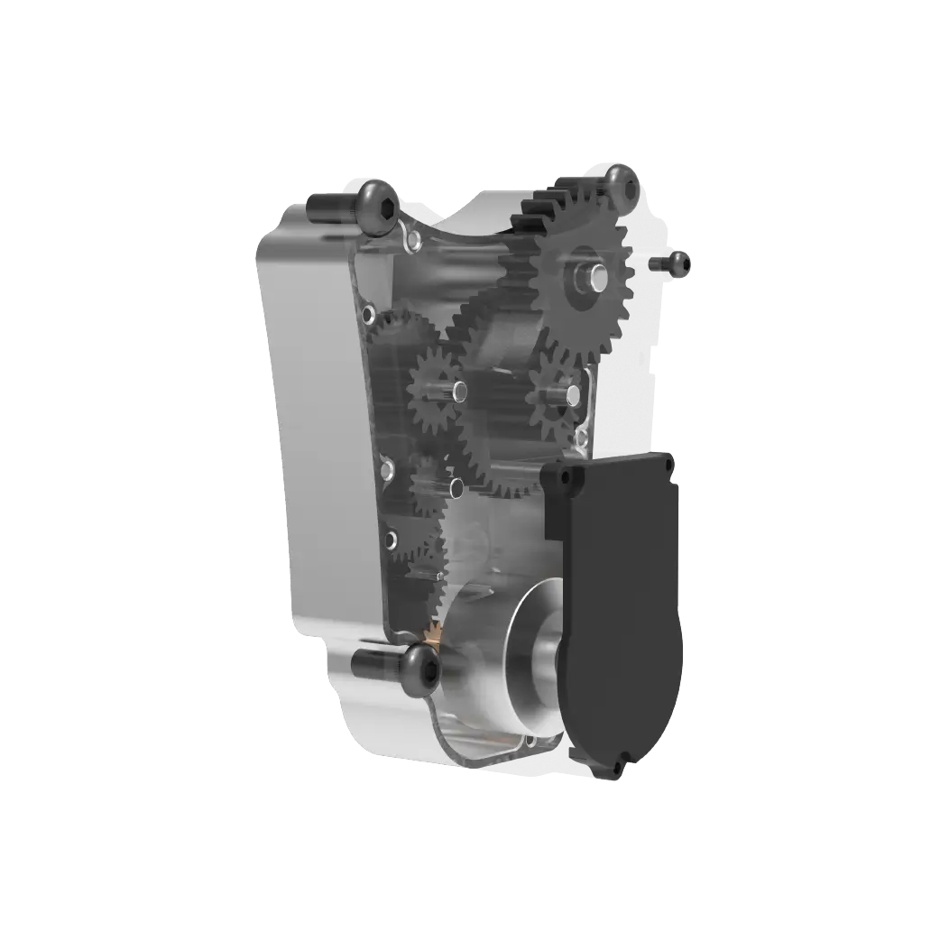
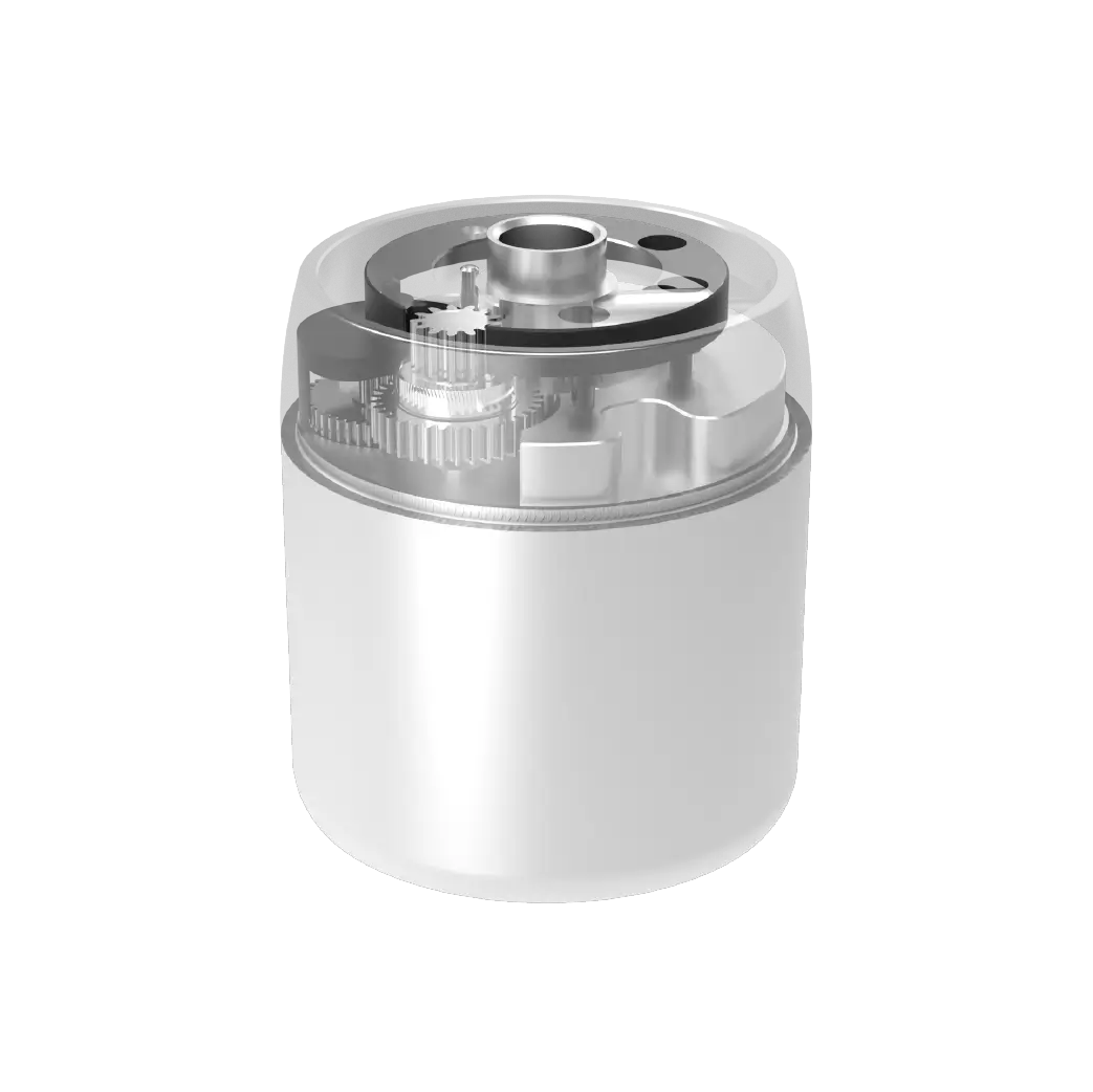
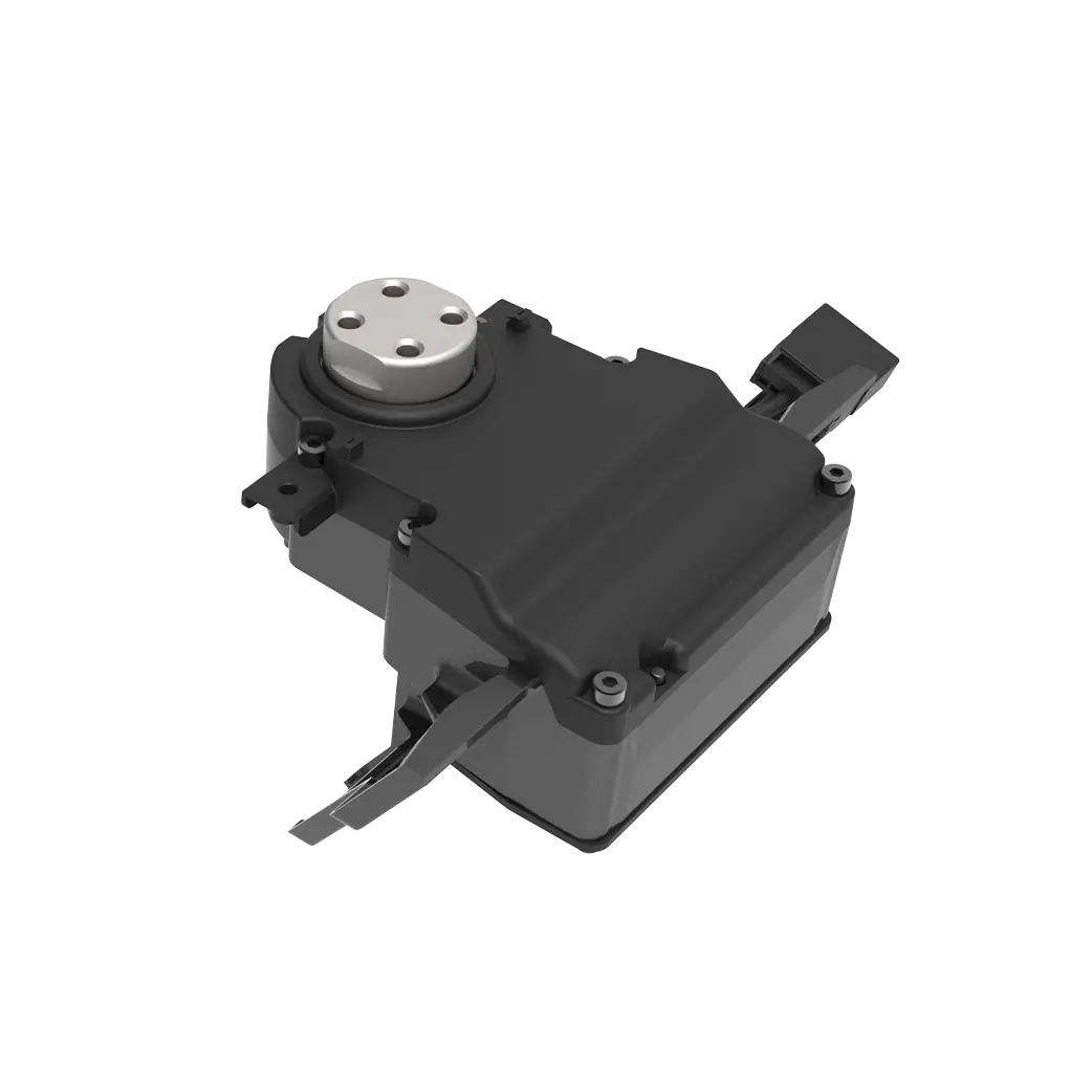
What makes an SG90 3D “easy to use”? It must include at least a few key details: the complete housing outline, the exact location of the output shaft, the precise diameter and spacing of the four mounting holes, and the shape of the three metal retaining lugs. A good one will even show the slight bulges in the gearbox section - these details are often the hidden danger points for interference.
Finding the right one is sometimes like looking for the right screw
Some people choose to do their own modeling. But this means that you have to take calipers and repeatedly measure, sketch, calibrate, and adjust again... especially those curved surfaces in the gearbox, which can keep you busy for a whole day. Another option is to find an existing, trusted document. At this time you will consider: Is the source reliable? Is the version updated? Has anyone verified it?
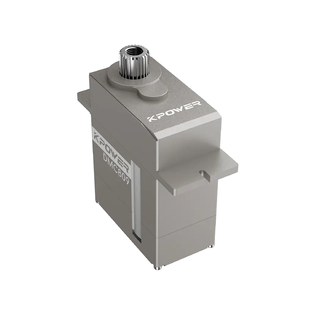
I recently came across a set fromkpowerSG90 micro servo 3D library. It impressed me a lot - not because of the brand itself, but because of the "just right" feeling. For example, the tiny indentation on the back of its fixed ears has been made, which allowed me to reserve just enough space when designing the bracket. The format is also very friendly, both step and iges files are included, and can be directly thrown into various CAD software for use.
Let’s talk about the actual experience of using it.
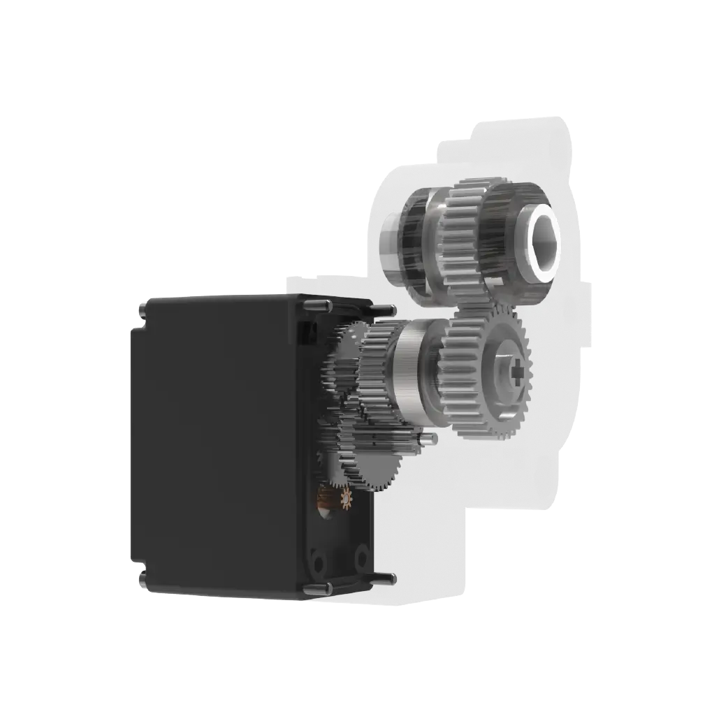
Once I helped a friend debug a small mechanical claw. The opening and closing of the claw was driven by two SG90s. In the previous one, the orientation of the D-shaped groove of the output shaft was 90 degrees different from the actual servo. As a result, everything was normal during virtual assembly, but after the physical assembly, it was found that the direction of rotation was reversed. Later, I changed a set and re-simulated, and the problem became clear immediately: it turned out that the axis position mark inside was inconsistent with the direction of the actual servo mark. This kind of detail is precisely the most easily overlooked and most time-consuming pitfall.
So you see, a good 3D doesn't just "look right", it also has to "move right". It can help you predict the rotation limit, calculate the load position, and even plan the cable routing space in advance - for small servos like the SG90, which are commonly used in compact spaces, how the wire is wound may affect the final action.
Some immature suggestions
If you are also looking for this kind of thing, you might as well think about it first: What are you using it for? Is it purely appearance rendering, or motion simulation? The former pays more attention to the outer contour, while the latter pursues accurate internal structure and size. Pay attention to the update situation. Products occasionally have minor revisions, and corresponding adjustments should be made simultaneously. Try testing it virtually in an actual project - for example, simulating a full rotation in the software to see if there are any abnormal collision prompts.
At the end of the day, the right tools make things easier. It's like having an accurate map in your hand, and you feel at ease when walking. In the small world of machinery, sometimes a reliable 3D picture can save you from detours.
Next time you are wondering how to install the SG90 servo, maybe you can try to start with a precise one. Drag it into your design software, rotate, enlarge, and assemble... Smoothness in the virtual world often means ease in real-life assembly. And this calmness may be the best starting point to push a small project forward.
Established in 2005,kpowerhas been dedicated to a professional compact motion unit manufacturer, headquartered in Dongguan, Guangdong Province, China. Leveraging innovations in modular drive technology,kpowerintegrates high-performance motors, precision reducers, and multi-protocol control systems to provide efficient and customized smart drive system solutions. Kpower has delivered professional drive system solutions to over 500 enterprise clients globally with products covering various fields such as Smart Home Systems, Automatic Electronics, Robotics, Precision Agriculture, Drones, and Industrial Automation.
Update Time:2026-01-19
Contact Kpower's product specialist to recommend suitable motor or gearbox for your product.


