


TECHNICAL SUPPORT


Published 2026-05-14
In 2015, there were many electronic enthusiasts who had just started to get in touch with open source hardware. For the first time, they posted in the community their rudimentary works of usingArduino PWM to control the steering gearto complete the steering of the car. At that time, the penetration rate of kits that could achieve this function in the hands of ordinary electronic enthusiasts was less than 12%. More people were stuck at the node of not knowing how to match the PWM signal and the working logic of the steering gear.
In 2018, public training data from university electronic innovation laboratories were displayed. The data showed that more than 72% of junior mechanical and electrical students were able to independently write basic steering gear control programs. However, 31% of users still experienced abnormal problems such as steering gear buffeting and steering arm jamming. At the same time, the industry has gradually sorted out common calibration methods.
In 2022, when the statistics of entries in the National Youth Electronic Technology Innovation Competition were conducted, the application of arduino pwm control rudder-related functions accounted for 47% of the actuator types of all entries. This technology has gone from a niche hardware gameplay to a highly popular basic training content.
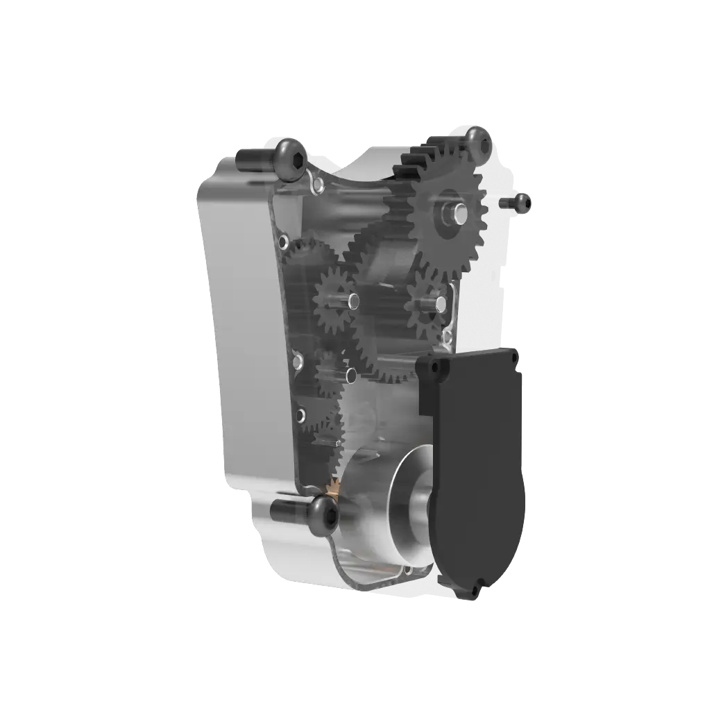
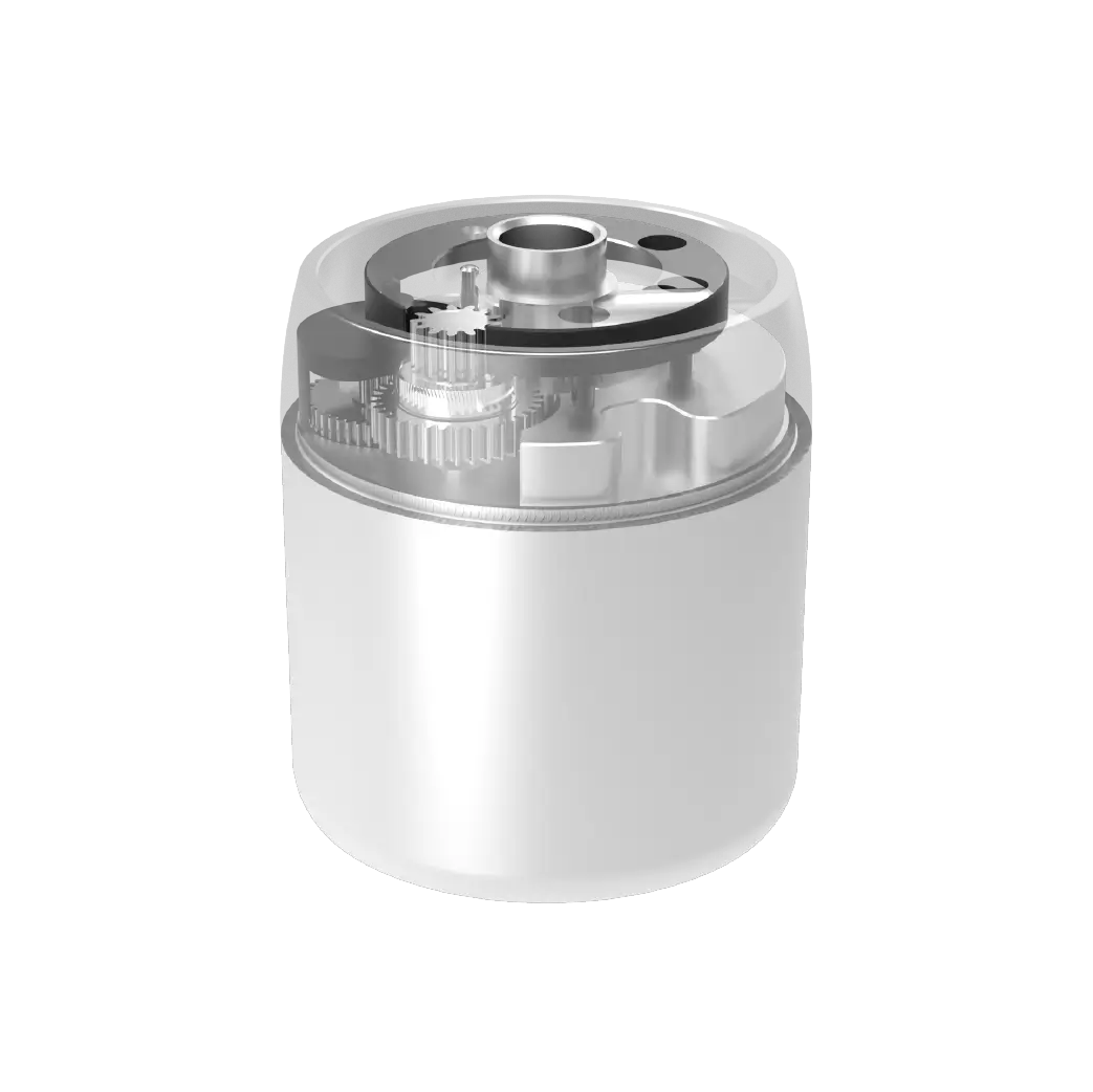
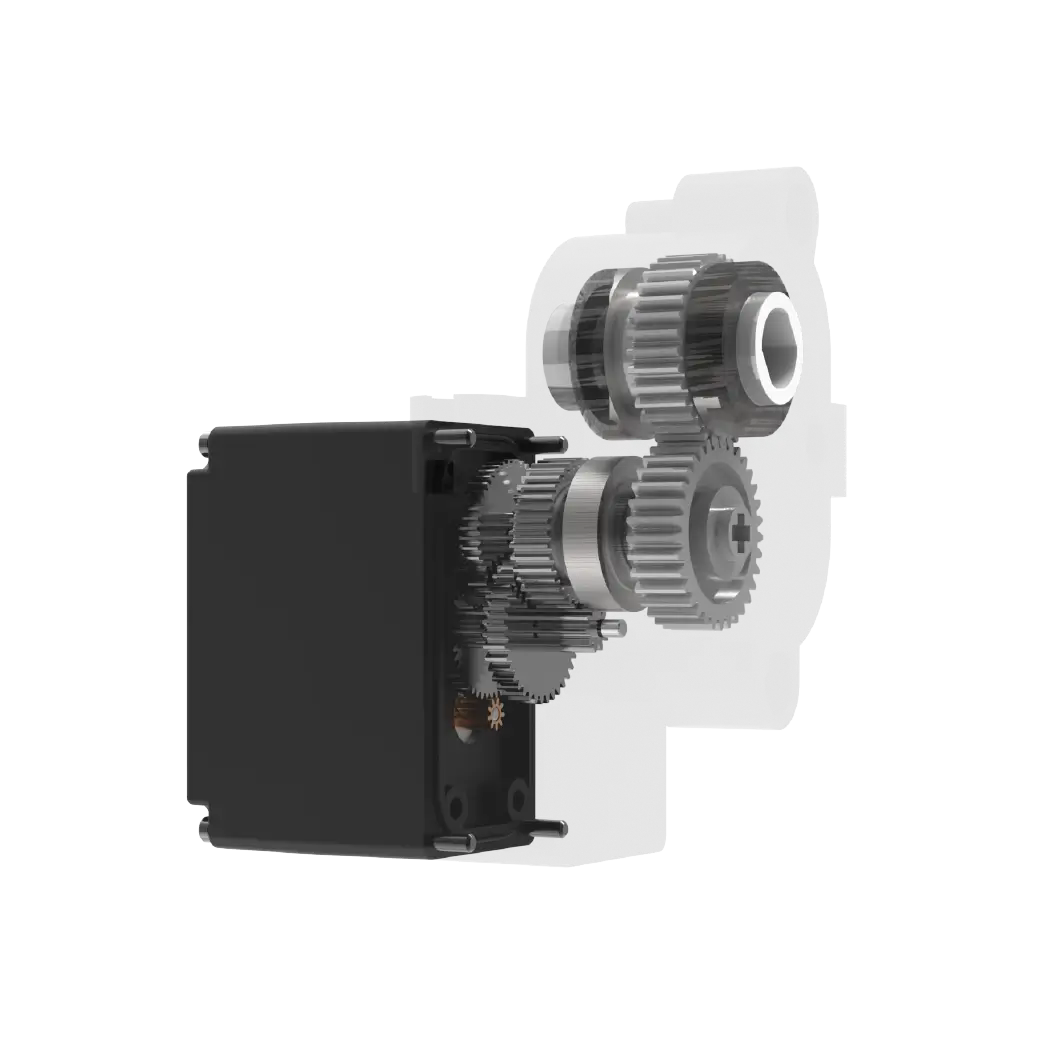
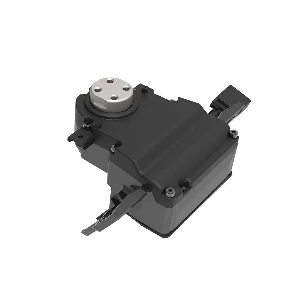
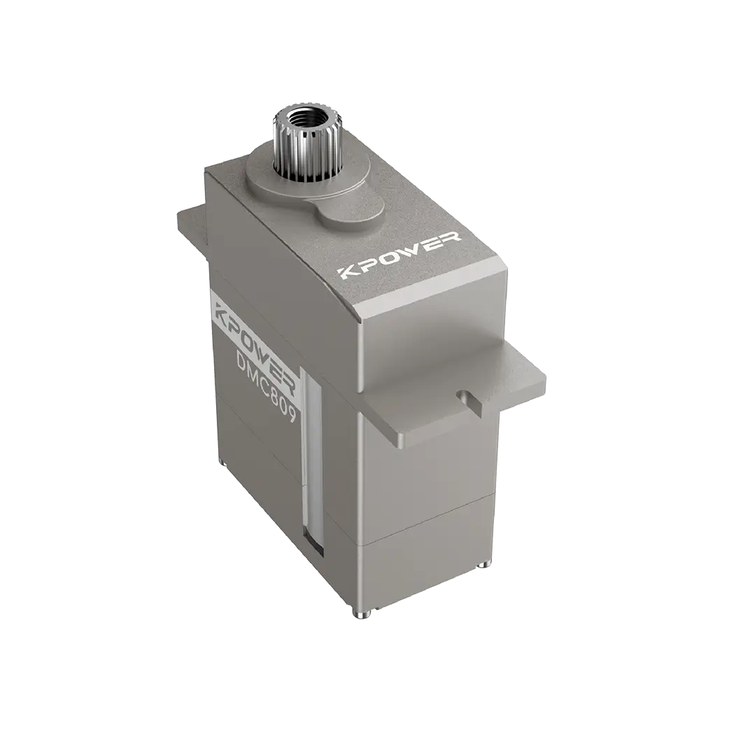
Set the time in 2026. For ordinary people, it only takes twenty minutes to complete the entire process from hardware wiring to functional debugging, and the entire process does not require complex professional background. Behind this is the feasible experience summarized step by step by countless enthusiasts and practitioners. The most basic hardware preparations need to be made. The standard working logic of ordinary 9gservos is to expect a PWM signal with a period of 20 milliseconds. The single pulse width is in the range of 0.5 milliseconds to 2.5 milliseconds, which corresponds to the range of the steering arm from 0 degrees to 180 degrees. Find a commonly usedkpowerThe 9g standard version ofservocan meet the needs of most entry-level projects. When wiring the hardware, connect the signal pin of theservoto the digital pin of the Arduino development board that supports PWM output, connect the power cord to the 5V power supply pin, and the ground wire and the development board share the ground, completing the most basic physical connection.
To complete the most core programming, you do not need to write complex underlying code such as timer configuration from the beginning. Introduce the Servo library officially integrated by Arduino into the development environment, define each servo control object, and call the attach function in the setup function to write the corresponding Pin binding, call the write function in the loop function and transfer the angle parameters you want to rotate, download it to the development board to make the servo rotate. Feedback from a platform that has accumulated 120,000 entry-level projects over five years shows that the one-term running success rate of this limited basic code can reach 89%. return. Don't underestimate this simple code with a few lines. It just touches the most critical signal adaptation logic ofArduino PWM control servo. It puts aside redundant functions and accurately transmits the effective pulse signal that the servo can recognize. Many people initially skipped the basic code debugging and went directly to complex control, only to continue to have problems.
In order to deal with the most common abnormal situation that people encounter, many people will encounter the situation where the servo continues to vibrate and oscillate once it is powered on when operating it for the first time. After taking it apart and measuring the PWM waveform output by the signal pin, the common reasons are either that the instantaneous voltage drop of the power supply exceeds 0.3V, which triggers the built-in undervoltage protection of the servo, or that the pulse parameters in the code are written incorrectly, causing the output signal to repeatedly jump at the edge of the threshold that the servo can recognize. According to statistics on relevant training data, 63% of the various faults encountered by entry-level users are caused by insufficient power supply. Just connect an additional external power supply with a voltage of 5V to the servo and ensure that the negative pole of the power supply line of the servo and the negative pole of the Arduino development board are firmly connected together to connect the common ground. In this way, more than 90% of the chattering problems can be solved immediately. This is the foundation for all advanced gameplay. You need to adjust the basic angle control smoothly first, so that more interesting creative functions can be extended step by step. Whether you want to add a potentiometer to the servo to achieve manual control, or add an ultrasonic sensor to achieve a linkage effect of automatic triggering of the servo opening and closing the door, ensure that the foundation is stable, so that subsequent expansion will not present a series of frustrations. According to the application scenario, the parameters of the program transplantation should be calibrated. The same model of servos of different brands will have a stroke deviation of about 5%. If the angle=90 command is passed under the same conditions, the actual angle obtained by the corresponding servo rotation will differ by 6 to 8 degrees. At this time, the universal fixation of 0.5 milliseconds corresponding to 0 degrees cannot be applied. Parameters, but to make a custom mapping log for the corresponding servo in hand, adjust the measured minimum pulse width and maximum pulse width to the actual calibrated values and write them into the function parameters. In this way, the civilian requirement level for positioning accuracy related to the application scenario can be raised from the original ±5° to ±1°.
Attached here is a full-step practical inspection process. Follow this process and check off each item one by one. After completing it, you will most likely be able to adjust the functions at once. Don’t skip steps or miss any item.
The first step of hardware verification
Make sure that the power supplied by the servo power cord can reach the five volts required by the servo, and that the ripple does not exceed 50 millivolts.
Make sure that the three wires do not connect the S, V, and G pins in the wrong order.
To confirm, the Arduino development board corresponds to digital pins that support PWM output, and most of them are interfaces marked with the ~ symbol.
The second step is full code inspection
Confirm that there is no version compatibility conflict in the official Servo library in the library manager.
Verify that the attached, filled, and programmed pin numbers, as well as the actual wiring and PWM output, can correspond.
It is confirmed that the value passed to the angle by write is limited to the range of 0 to 180, there will be no overflow, and there will be no logical illegal parameter transfer.
The third step is to do the debugging and troubleshooting process

First upload the simplest sample code to test whether the rudder performance can return to the neutral position and operate normally without abnormal lag.
Connect the logic analyzer to the corresponding output pin, measure the actual output PWM waveform, and determine whether it is a qualified period of 20ms, right?
At the beginning, do not rush to carry out operations involving dynamic coordination of multiple servos, trajectory smoothing and other advanced functional gameplay. Instead, set a servo to a fixed angle and run it in a forward and reverse cycle for an hour to check whether it is stable. Many enthusiasts who have just started to get started have only reached the third step and hurriedly jumped a dozen steps away. After encountering a problem, they went back to the source to find the root cause. After spending several days, they still couldn't find where the error occurred. In this way, they took a big detour, and it was really not worth the gain. In a common small garden that can automatically sprinkle water in a directional manner, when setting the motions of the joints of a desktop-level small mechanical doll,arduino The pwm control servocan cover more than 80% of the lightweight mechanical execution scenarios that ordinary creators can think of. This set of basic circuits seems to be relatively simple to get started, and the code logic can also present more interesting and fun possibilities when delving deeper. Through cross-point sensing data collection and PID algorithms, they can be combined with each other. It is equipped with operations to implement control and achieve point reproduction with near-industrial-level precision at a low cost. Previously, someone made a robotic arm project for desktop-level writing, which is to superimpose this core underlying control logic layer by layer. The finished product cost less than 100 yuan to achieve the actual effect of position control accuracy of ±0.8 mm. It has also been widely circulated in enthusiast communities and has been forwarded one after another.
Don’t believe it, it’s just such inconspicuous small solutions that gradually accumulate and build wonderful applications. Who claims that the fun and playability of open source hardware cannot be achieved at the same time?
Collect the practical questions that everyone asks the most, organize them, make them into Q/A, and list them so that they can be quickly, searched, and consulted:
Question: By using a normal duty cycle to simulate output pins, is it possible to control multiple servos without expansion modules to rotate simultaneously?
Regarding the situation mentioned by A, it is not allowed. Because Uno, with AVR as its core, has limited hardware PWM pin resources, it will prioritize key signals that control frequency.
Q: After the direct download of the program is completed, the servo will automatically vibrate and will not be controlled by written commands.
A. Check the power supply line to see if there is a weak connection in the main line of the common ground. In many cases, the common ground becomes invalid. This situation will cause the servos to obtain mutually mistaken pulse signals.
Q: What should I do if the rudder angle positioning cannot reach the exact angle I calculated and wanted?
A: Manually calibrate the PWM pulse width, remove the dummy bits of the structure and then re-determine the parameters. Do not just apply the common parameter scripts on the Internet without thinking.
When the development board itself is used to provide the power source and is directly connected to the rudder for power supply, why does the operation appear to be laggy and the power supply is easily prone to backfeedback?
When the servo is started, its peak value exceeds 600mA. The onboard LDO cannot withstand the instantaneous load voltage drop, so an external independent power supply is required to stabilize the power supply.
The core of these points that have been repeatedly emphasized are still the ones mentioned over and over again: the underlying principle ofarduino pwm control of the servo, the matching of the definition of the PWM period of 20ms, the matching of the corresponding pulse width of the pulse and the mapping of the actual rudder angle, independent power supply and ensuring that both sides are grounded, this is the key point to avoid pitfalls. Don’t ignore the practical conclusions that many big guys have accumulated through pitfalls. You must fulfill these three core prerequisites honestly. 99% of ordinary beginners will not need to find any high-end complex special tools. Finally, everyone should start now, take out the kit materials, and spend fifteen minutes to follow this set of practical procedures. At the beginning, we should start with the simplest forward and reverse cycle test of a single servo, and let it run first, instead of pondering the results over and over in the mind, but never actually doing it in person, such as welding circuits, writing programs, just watching tutorial videos, talking about it without actually doing it, and you will never get it done. Understand exactly where the small pain points in practical operation are stuck. The moment you turn the servo with your own hands to make it turn, all the abstract feelings of theoretical study on paper will be completely eliminated. Isn't this the kind of pleasure that fans of open source hardware first experience? Having said that, if you are going to actually operate it now, what is the first function you plan to use the servo to achieve in your first project?
Update Time:2026-05-14
Contact Kpower's product specialist to recommend suitable motor or gearbox for your product.


