


TECHNICAL SUPPORT


Published 2026-05-13
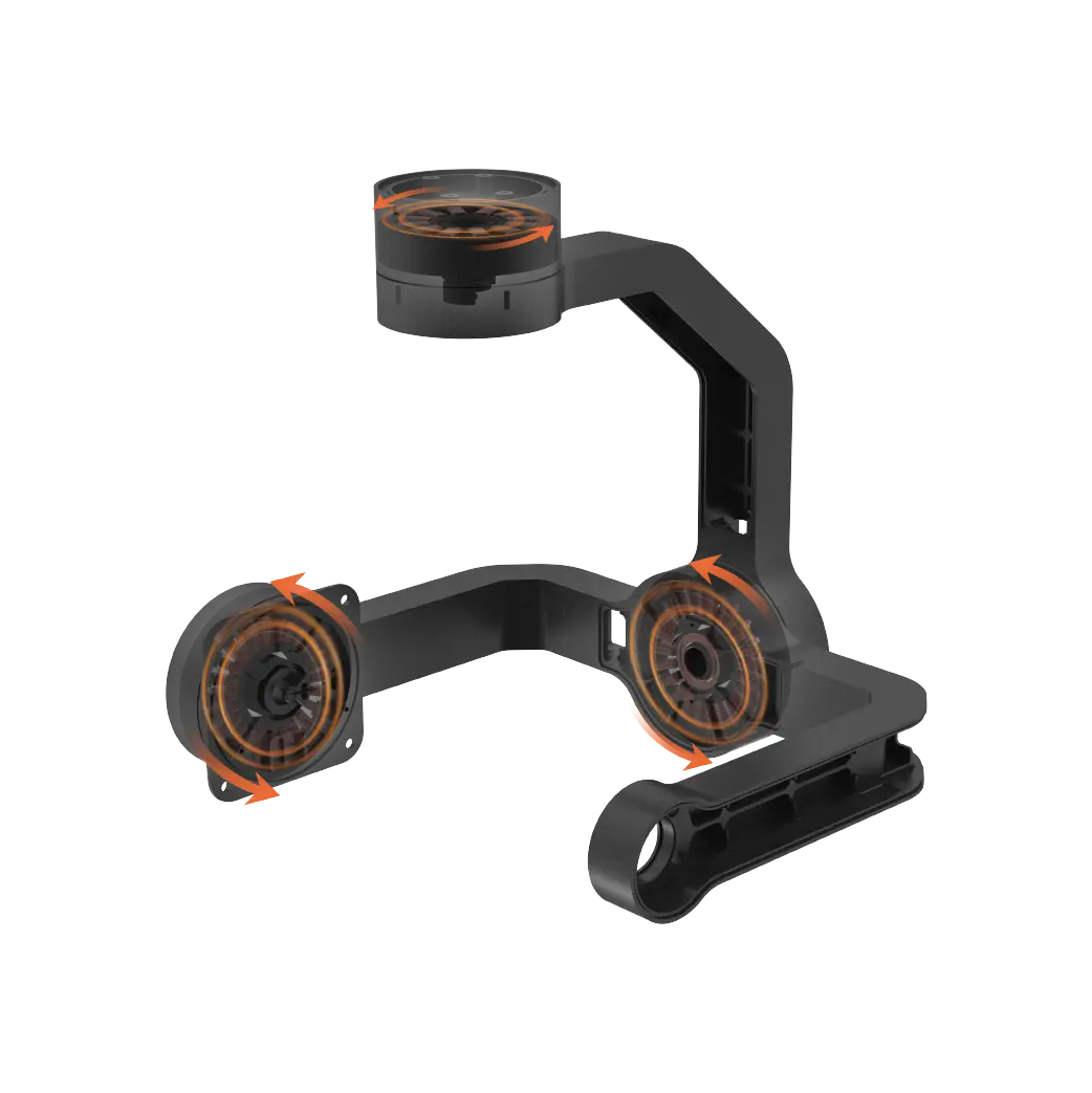
It is most appropriate to apply the ancient adage "a slight difference makes a difference of a thousand miles" to the setting of the steering gear. I once saw a six-axis robotic arm, because the zero point was offset by 3 degrees, forced cracks out of the workpiece when grabbing precision components. This was not only a loss of several hundred yuan, but also a profound questioning of the word "standard". The zero-degree position of the steering gear is not an approximate value that can be discussed. , but an absolute reference that is locked together by mechanics, electricity and protocols. If the servo is the joint of the robot's limbs, then Zero Degree is the part called the "clavicle" that determines the starting point of all movements. It is miscalibrated. As a result, the subsequent series of angle mappings will be toppled like dominoes, the torque output will also be toppled, and the trajectory planning will also be toppled.
So, what specific hard requirements does a zero-degree setting that meets industry standards cover? We can further disassemble the steering gear into three core subsystems, namely the potentiometer feedback network, the PWM analysis logic of the control chip, and the mechanical limit of the gear set. Any deviation on either side will be "repeatedly amplified" at the zero point. This is why senior engineers always say "reset to zero first, then install the machine".
Level 1: Absolute anchoring of the electrical zero point
Each digital servo follows an underlying contract. This contract regards the PWM pulse width of 1500μs as the theoretical position. However, manufacturing tolerances cause the "true neutral" of each servo to be in the range of 1450μs to 1550μs. The core action of the standard specification is to perform a "potentiometer zero self-learning". The operation path is extremely clear. Place the servo in the no-load state, input a 1500μs signal that lasts for more than 2 seconds, and then complete a full-scale forward and reverse stroke within 3 seconds, such as from 1000μs to 2000μs, and finally return to 1500μs. At this time, the MCU inside the servo will record the AD sampling value of the potentiometer at this moment and lock it to the "physical zero position". If you skip this process, your servo will never know where "neutral" is. A common situation is that an aircraft model enthusiast directly performs the frequency linking operation when assembling the fixed wing, and then installs the rudder arm. However, such a situation occurs, that is, when the aileron is at the midpoint position, the left and right rudder surfaces are 5 degrees different. The actual reason is that he has never allowed the servos to learn their own zero point.
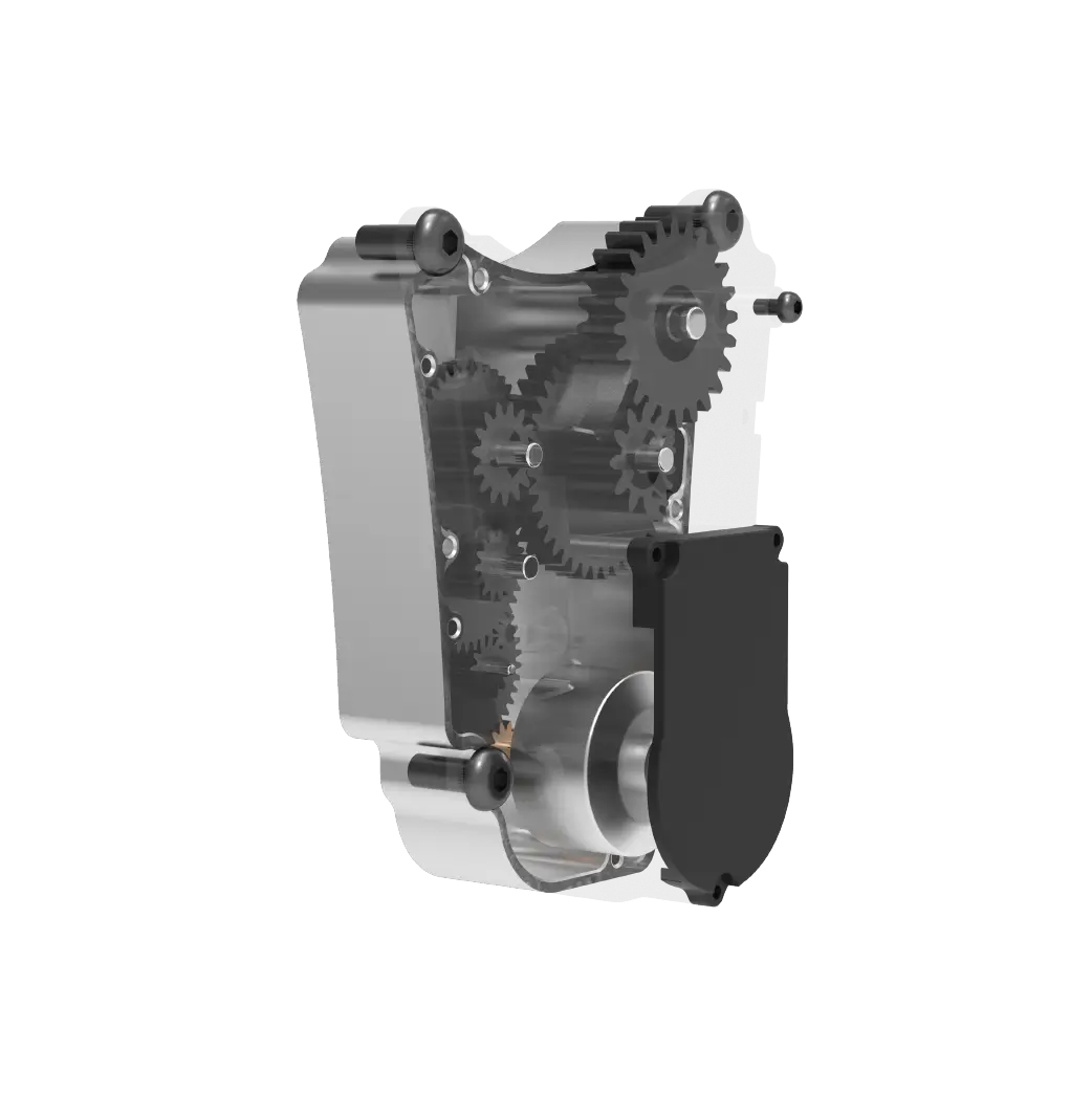
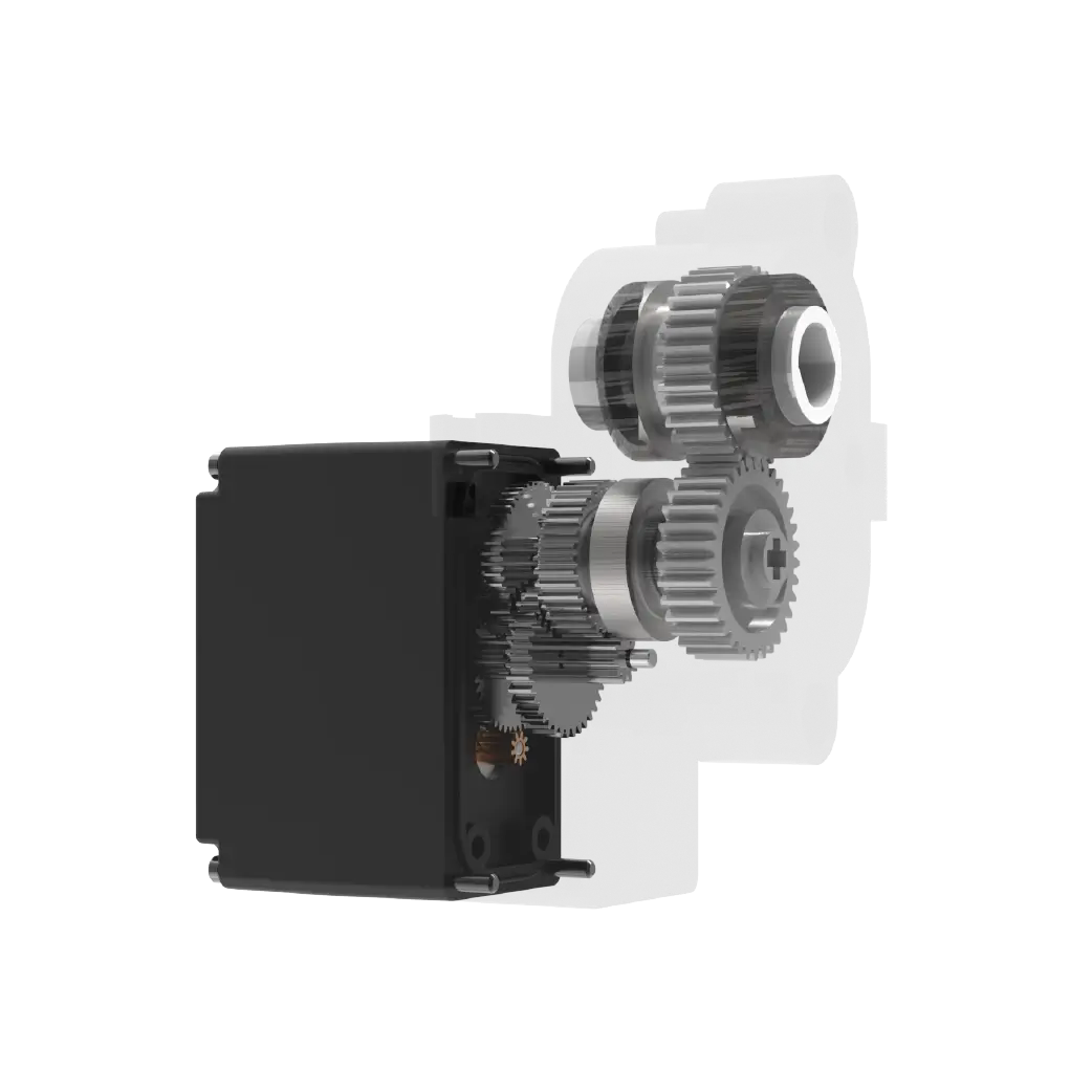
Second level: redundant avoidance of mechanical limits
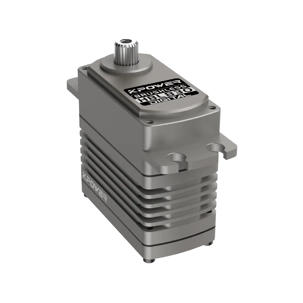
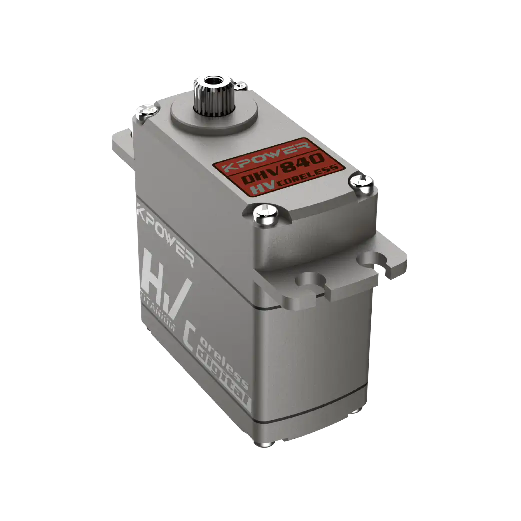
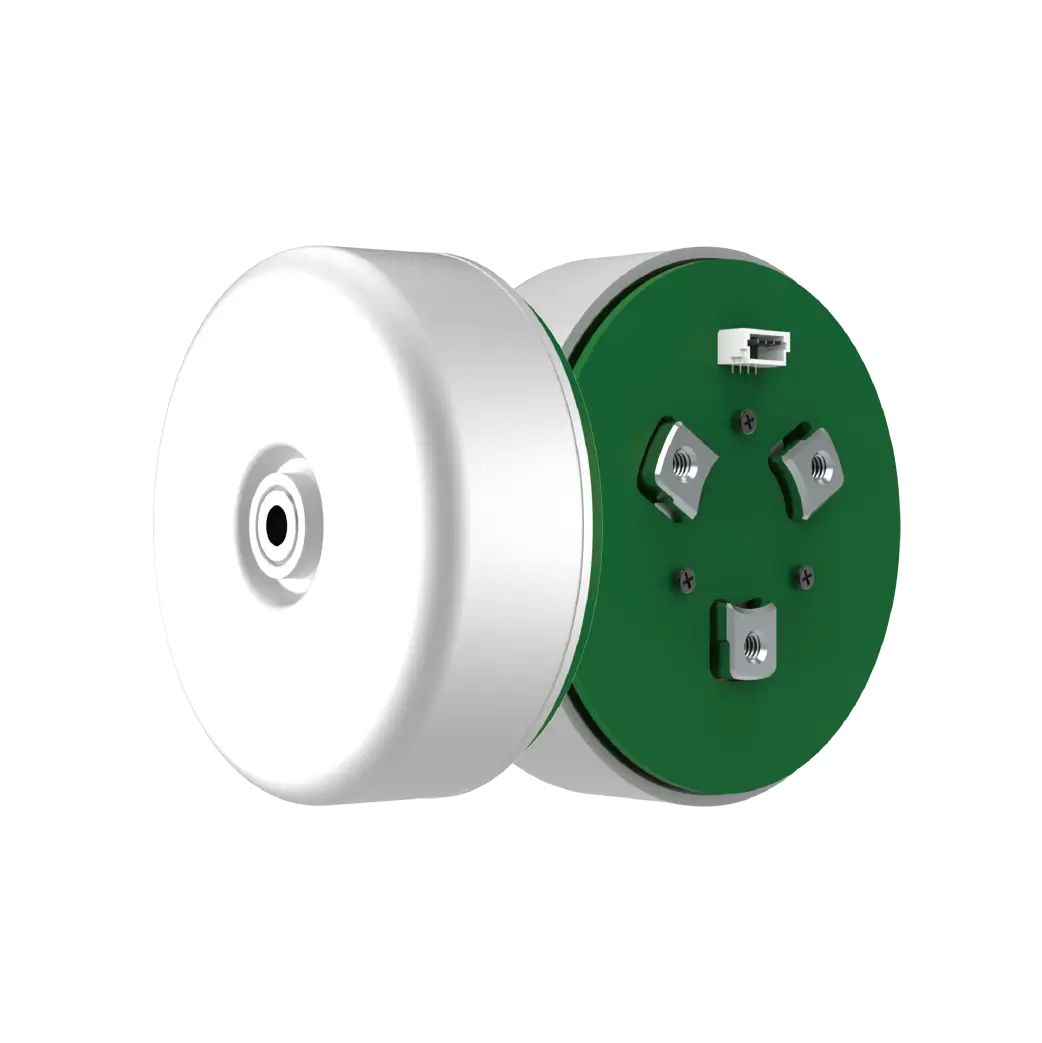
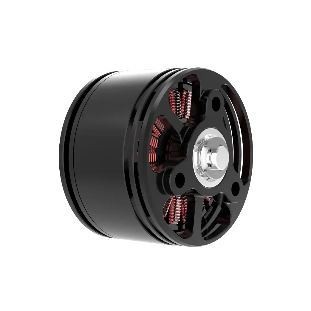
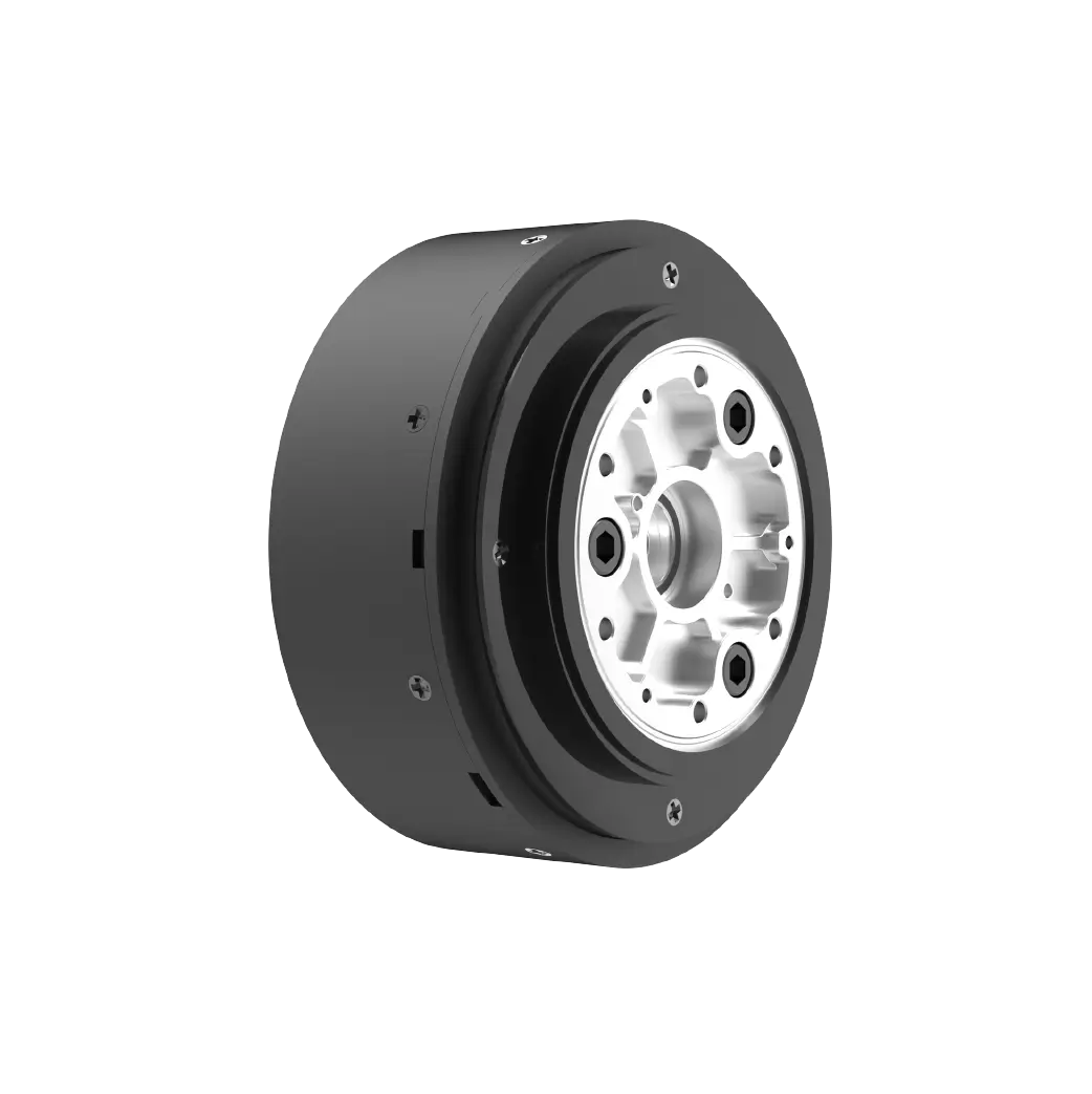
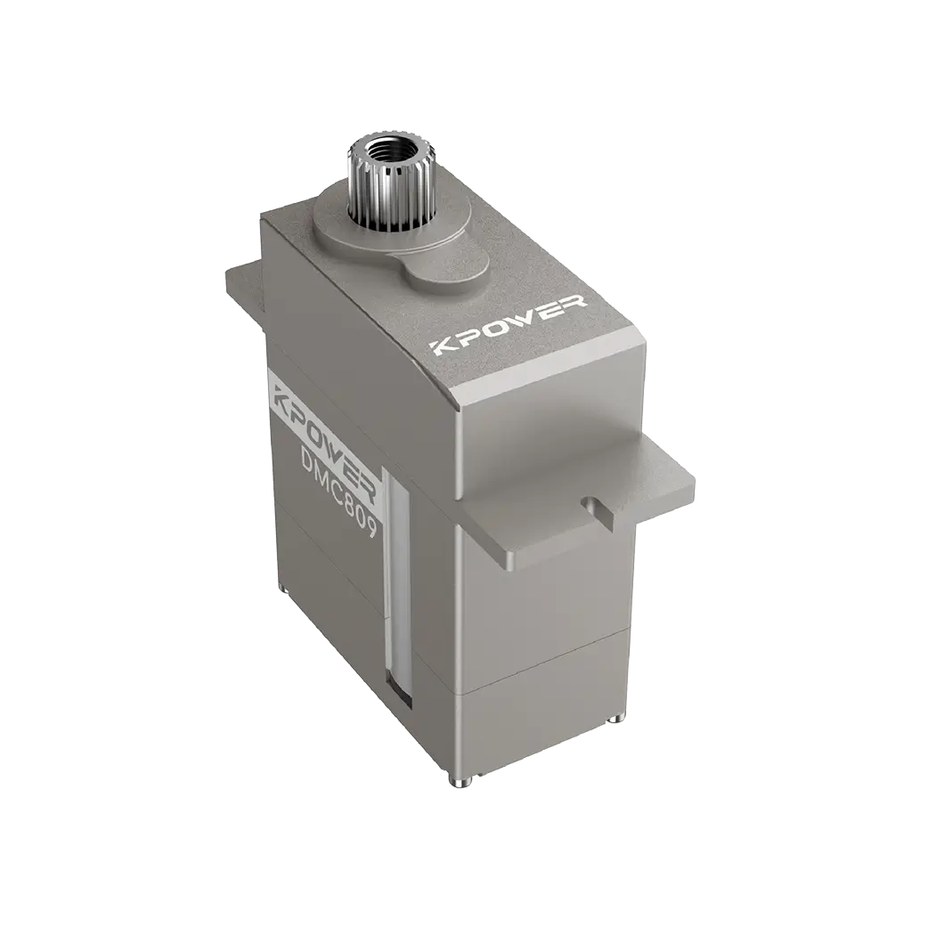
Even if the electrical zero point has been locked, the gear set may still bring about a "false zero position" on the physical level. The standard requires that when the servo is in the zero position, the tooth tip of the output spline must be aligned with the marking groove on the housing, just likekpowerThe Servo's titanium shell has V-shaped grooves carved into it. But more importantly, you must manually verify whether the limit travel in the left and right directions is symmetrical.Suppose there is a servo with a nominal ±45 degrees, but when it rotates to the right at the zero point and reaches 42 degrees, it stalls, but it can turn to the left to 47 degrees, which indicates that there is a deviation in the gear assembly.. If it is used forcibly at this time, in a mild case it will only cause the range of motion to not reach the extent it should be, but in a severe case it will burn out the drive MOS tube. The true zero-degree state is to touch the limit posts gently on the left and right sides, but there will never be a deadlock situation, it is just at such a balanced point. I once saw a contestant participating in a robot competition. Because he ignored this point, the mechanical leg he controlled always swayed to the right during the walking process. Finally, at the finals site, the servo became stuck and no longer worked, so it had to be scrapped.
Layer 3: Protocol synchronization and external tool chain
As we enter 2026, CAN bus and serial port smart servos have replaced traditional PWM servos on a large scale. Their zero setting status is not the same as before "give a pulse", but to write a specific value to the register.There are clear requirements in the standard specification: the main control board must be used to send a "zero point calibration command frame" - generally speaking, it is a hexadecimal data packet like 0x55 0xAA 0x03 0x01 0x00 0x02. The last two digits here mean "set the current position to 0"。Before operation, be sure to disconnect all load links and confirm the returned response frame through the serial monitor, such as 0x55 0xAA 0x01 0x00 means the writing is successful. A typical fault case is that a developer called the setPosition(0) command in the ROS environment, only to find that the servo was shaking slightly. This was because the code incorrectly interpreted "target angle 0" as "forced output 1500 μs", but did not first read the current physical offset of the servo. Before performing a zero point write, the specification requires that the current position be read at least three times, averaged, and then subtracted to compensate.
Frequently Asked Questions Q/A
Q: What should I do if the servo makes a hissing sound when setting the zero point?

A: Cut off the power immediately. This is the overload sound made when the gears collide with each other and hit the limit. It is necessary to manually turn the spline to align the teeth again before calibrating.
Q: Is it normal for the zero temperature to drift by 1-2 degrees every time it is powered on?
A: Showing an abnormal state. Check whether the power supply voltage is lower than 4.8V, or check whether the potentiometer pins are soldered.
Q: Can I use a screwdriver to directly turn the output shaft to align the zero position?
A: Absolutely not, this will destroy the meshing phase of the internal reduction gear, leading to permanent errors.
Q: Can servos with different protocols use the same zero-point setting method?
A: No. PWM uses signals to learn, the serial port uses command frames, and CAN broadcasts through IDs. They are all incompatible with each other.
Suggestions for action: Turn Zero into a ritual
Every time I get a brand new servo, I will use a red marker to write three different dates on the outer shell of the servo, namely the date of electrical calibration, the date of mechanical tooth alignment, and the date of load verification. This is by no means formalism, but an anchor against forgetfulness and luck. You need to build your own checklist. One is to send a 1500μs signal in the no-load state. The second is to detect the rotation stroke so that the difference between the left and right limits is less than 1 degree. The third is to use a right-angle gauge to measure the verticality between the output arm and the steering gear housing. Fourth, under the maximum load condition, the temperature remains at zero for 15 minutes without any temperature rise. Remember: one precise zero setting is better than ten subsequent repairs after failure. The secret of those teams that win the competition and those robotic arms that have been stably operating on industrial production lines for tens of thousands of hours is just to repeat these three seemingly simple steps and become instinctive. At this moment, close this article and go check the zero point of the servo you have on hand - it will reward you with unwavering loyalty.
Update Time:2026-05-13
Contact Kpower's product specialist to recommend suitable motor or gearbox for your product.


