


TECHNICAL SUPPORT


Published 2026-05-13
May 12, 2026 Sunny Next to the bench of the tool shop on the street corner
Last weekend, I squatted in a tool shop in an old alley all afternoon. There was a little boy in school uniform next to me. He was holding a broken servo in his hand, and his fingers were rubbing the circuit board solder pads for a long time. He said that he was working on a quadruped robot with the school's science and technology innovation team two days ago. As soon as he got to the action debugging stage, the core servo got stuck. He couldn't afford the original machine sent back by Taobao. The circuit diagrams he searched online were all coded versions, and even the line sequence didn't match up. After staying up for three nights, the machine didn't start. He sat on the stool with his eyelids drooping to the table, and the corner of the Science and Technology Innovation Competition Entry Certificate that leaked out of his pocket was rubbed with hair.
When many ordinary people are tinkering with small power control projects, most of them have encountered such troubles: after taking apart the broken servo, they can't understand it at all, and they are looking for the internal circuit diagram until their hair is greasy, or the information they find has a different circuit sequence. Often, either key component parameters are missing, and it is difficult to even replace them in the end. Many people struggle to the end and directly throw the mostly usable parts into the corner of the storage box as scrap, which not only wastes money, but also accumulates a pile of semi-finished products that cannot be finished. Many hands-on people who have stepped into the pit have later accepted this "reality": without reliable reference materials, it is impossible to follow the circuit principles of the servo to slowly troubleshoot the problem. Blind trial and error not only consumes time, but also easily damages other intact parts of the motherboard. In the end, the entire frame of the project is completely scrapped, with no room for rescue, leaving half a day, and no room for advancement.
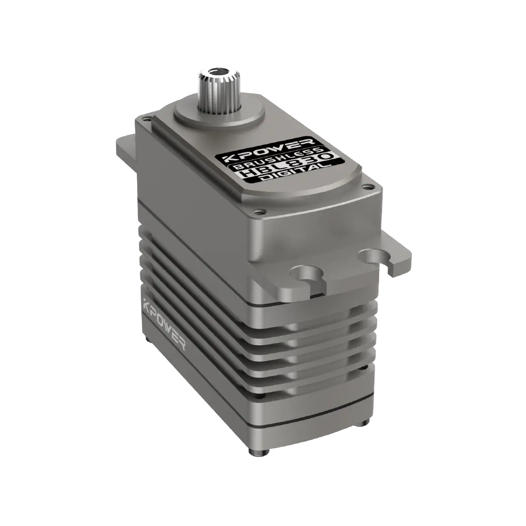
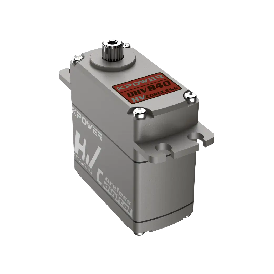
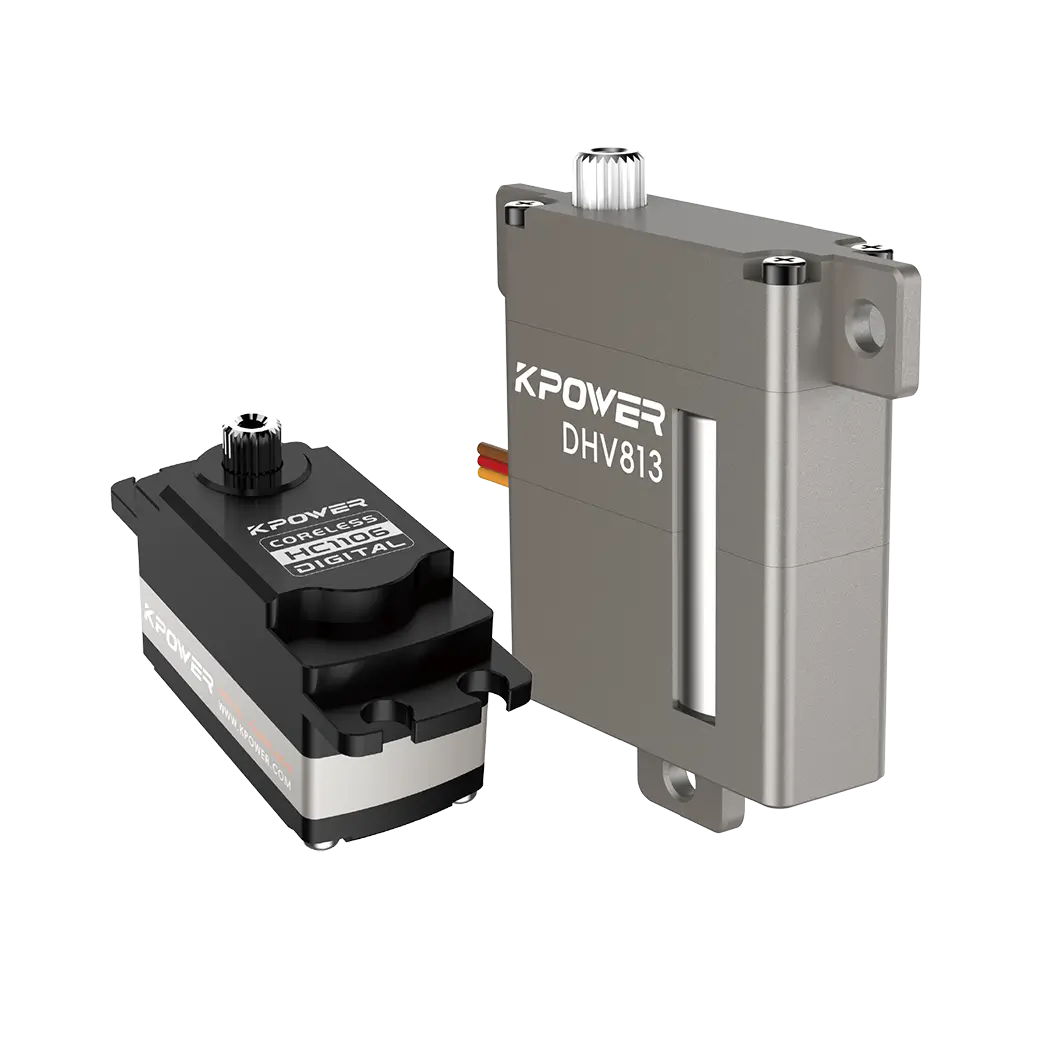
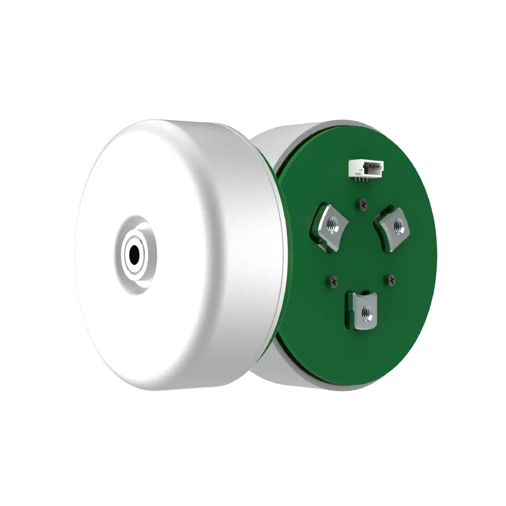
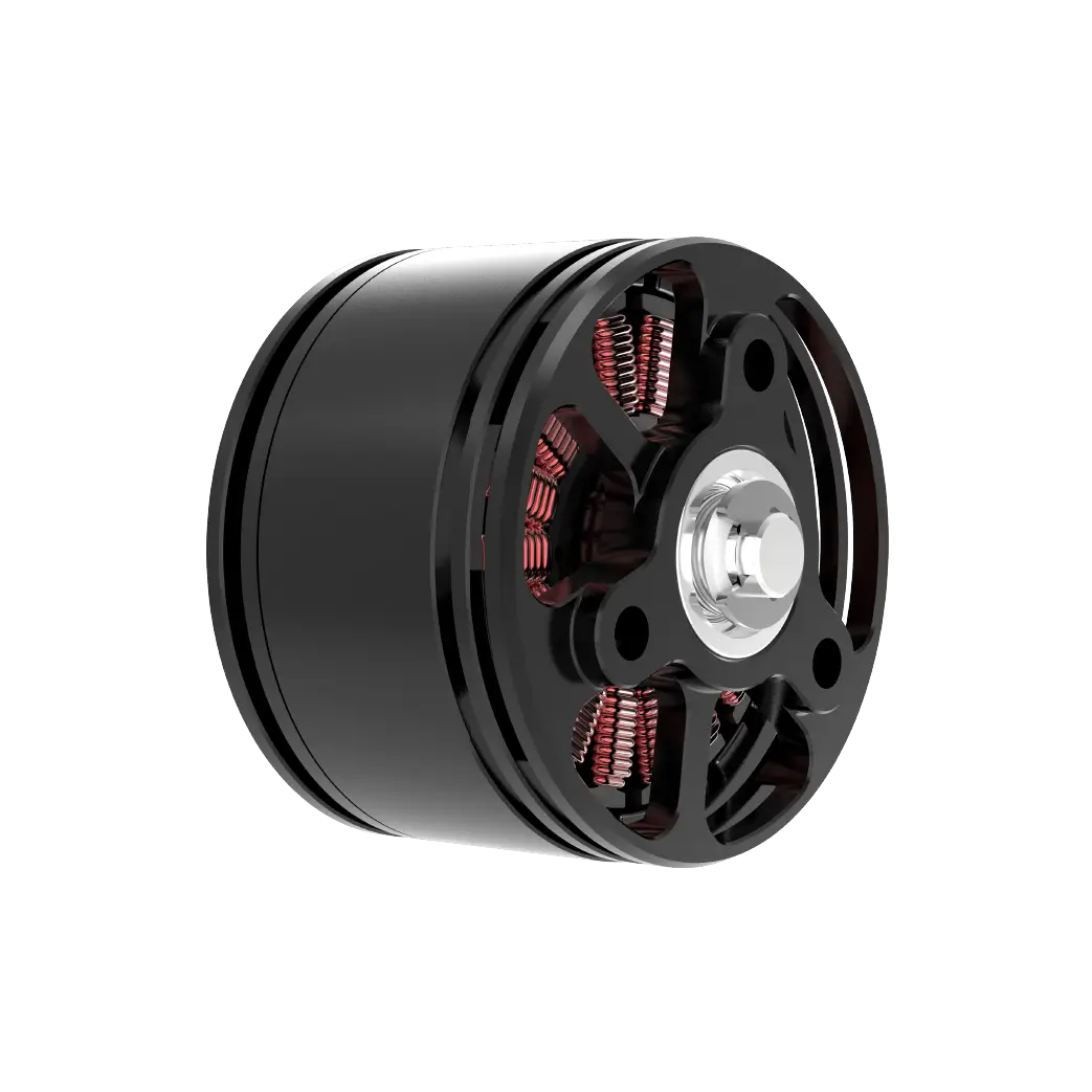
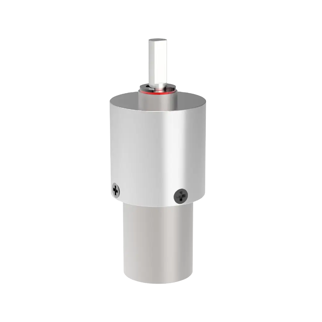
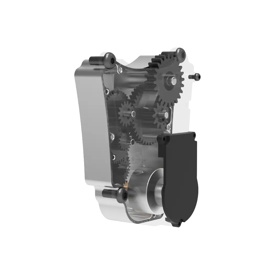
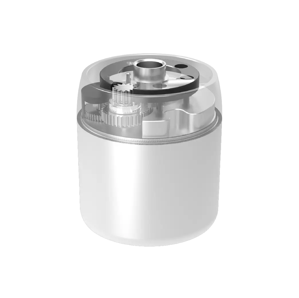
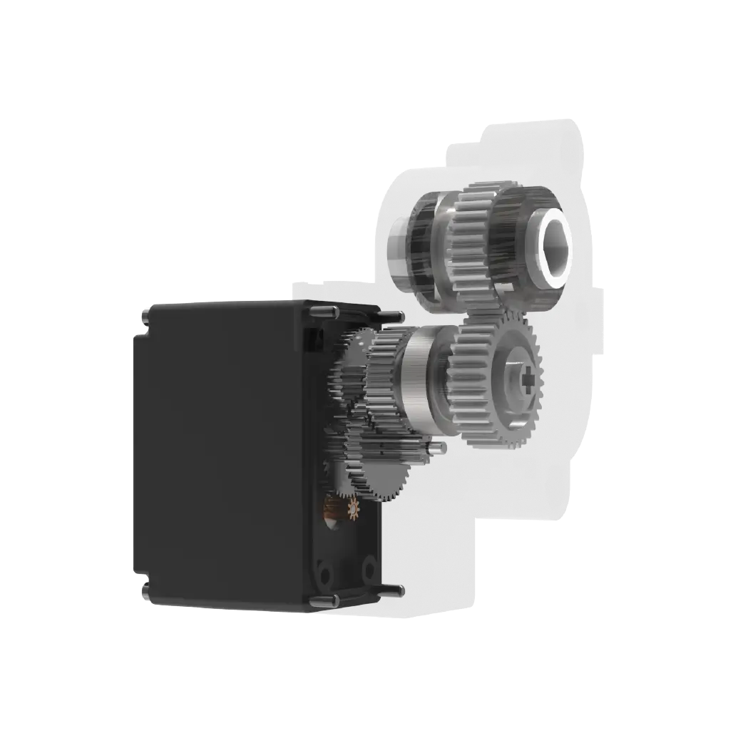
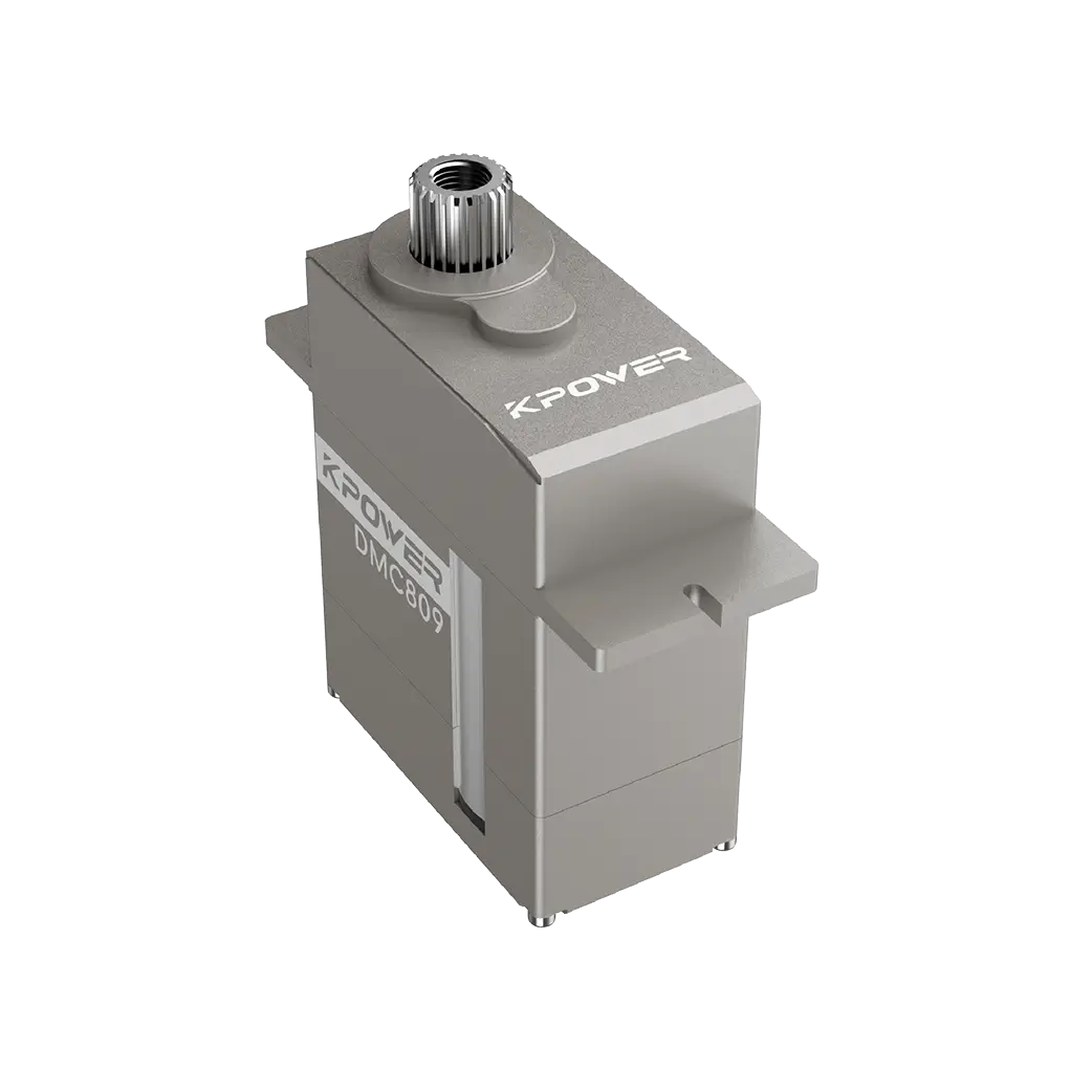
No matter what you are holding in your hand, it is used for steering small mechas, controlling flight movements of model aircraft, or is a common specification servo used for opening and closing automatic doors for small objects. Its internal circuit underlying structure is basically inseparable from several inevitable modules, namely the signal receiving area, the signal deviation calculation area, the power push area, and the power position feedback area. Just cite a situation that everyone often encounters. You are playing with a standard servo that weighs 15kg and has a metal tooth version with high torque. After taking it apart, you will find three external leads running along the edge of the circuit board. They correspond to the control signal positive, 5V power supply and ground positions respectively. In the drawing, this part of the wiring needs to be directly connected from the solder joint of the incoming wire to the signal pin position of the signal amplification chip. Here as long as there are If one wire is connected backwards, the servo will immediately stall when the power is connected, and you won't even get a power-on response. I once met an enthusiast who had just been in the game for half a month. He connected randomly according to half a vague line diagram. In the end, he burned out all three compatible interfaces around the main controller of the project that he bought at a huge price. The results of staying up late for half a month to accumulate power module accessories were all in vain, and he was busy in vain.Most novices will think that the drawings are difficult to understand at first. In fact, it is not that the circuits are complicated. The real reason is that the scattered data deliberately lacks the marking points corresponding to the positions of each module. You can count the physical parts for a long time, but the result still does not match the number of pins marked on the diagram. After repeated viewing, you cannot determine where the wrong wires are connected. Only relying on your own blind guessing costs money, and few people can afford it.。
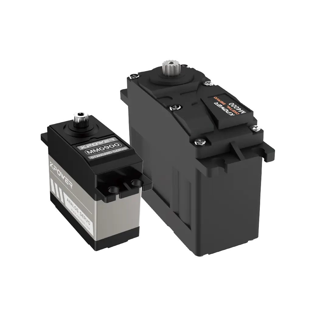
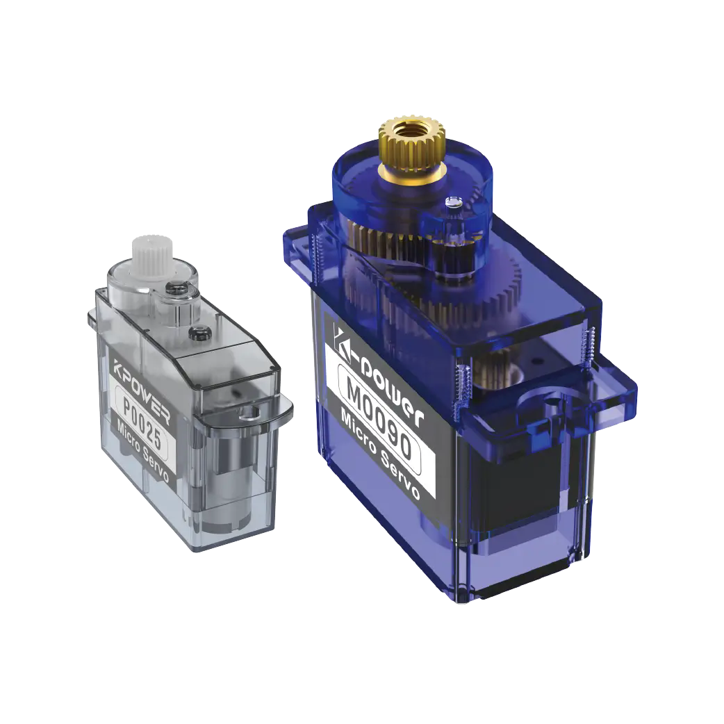
We went to visit offline communities where enthusiasts gather to communicate. After visiting, we sorted out nearly a hundred items, which are complete internal circuit drawings corresponding to the most circulated servos on the market. These servos are what ordinary people save for projects. The most commonly used, from the small digital micro 9g micro servo to the large-arm industrial servo with a high torque of tens of kilograms, from the old-fashioned servos used in simulation to the latest and popular new models with bus communication, all the drawings have been reviewed repeatedly. According to the actual parts, calibrate them one by one. The corresponding function and connection purpose of each pin, and the standard parameters of each resistor and capacitor are completely, clearly and accurately marked. Even common replacement parts can be replaced. The alternative values that do not affect normal running are all marked with marked intervals. After you get it, you don’t have to go around and check the line sequence while soldering. By following the marks, you can directly circle the fault point step by step and find the root cause.
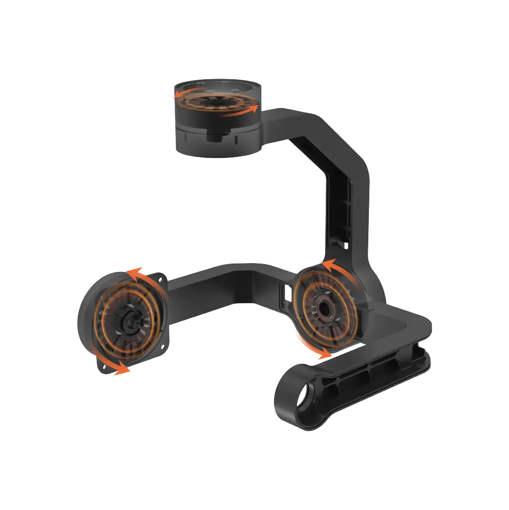
Here, we will share two examples. These two examples are real situations that have been repaired and are common in the community of model friends recently. They can be used as a reference. The first example is that there is an ordinary model friend in the garage downstairs of the community. He got an old and blurry steering gear drawing. This drawing did not mark the silk screen layer. He tested it repeatedly for three days on the old analog steering gear that had burned parts due to wrong voltage connection. After that, he found a complete set of drawings that we had compiled and proofread, and pushed the reference replacement model of part of the main control chip based on the power marked above. He spent more than ten yuan to find the goods from the aftermarket and replaced it. The servo was repaired that day, and he could fly after putting it back on the helicopter model. The entire cost of consumables for repairing parts was not even twenty-five yuan. However, if he had to buy a new one with the same The original brand new servo of the model costs at least 90 yuan. In this way, it directly saves at least two-thirds of the cost and more; the second example is that there is a little boy in the middle school extracurricular group who has just entered the first grade of junior high school. He assembled the moving parts of the humanoid exhibit for online puzzle competitions. Since the students have too much money, they can't use it all. The cost of buying a new original batch of servos is limited, so Using the compiled steering gear drawings, they dismantled more than a dozen old servos that others had discarded, selected compatible core parts, and welded them into three module groups. Finally, they assembled all 12 kinematic joints of the finished project so that it could run fully equipped. Finally, when the school went out to participate in the exhibition and debugged the entire machine, the machine never had a single motion jamming failure, which helped them successfully obtain the second-class municipal competition result.

The first type of audience is the novices who are still in the amateur stage of this field. There are no complex board-level operation debugging and deep board-level requirements. They only need to compare the key points of the silk-screen layer traces pre-marked on the drawings. First, explore according to the corresponding positions of the marks printed on the circuit board to confirm the fault point: For example, the servo in your hand does not respond after the power is turned on. At this time, do not rush to directly power up the test or blindly weld. You should first compare the incoming pin points on the drawing. Use a simple continuity meter to scan twice to check for interruption. When the resistance exceeds the upper limit marked on the drawing, it is basically the point where the wiring is burned or the fuse resistor breaks down; if the servo makes a whining sound and continues to vibrate after powering on, Stop and cannot go to the end position, then just follow the drawing prompts to find the potentiometer part under the position feedback module. There is a 90% probability that the voltage dividing parameter here is deviated. If it is not adjusted twice, it will not be restored immediately.According to the accurate and complete instructions, novices can start based on the reference drawings. Even the most basic component replacement tutorials are provided with supporting references to follow. There is no need to worry about more parts being burned due to blind attempts.。
Look at those people who compare in reverse, they don't have any reference in their hands, they just do it blindly. I have seen many enthusiasts connect the power cords backwards because they could not tell the location of the power incoming wires of the circuit. As a result, the normal electronic module next to them, which was not faulty, was burned through and died. As small as a driver chip, the whole thing bulged and exploded, completely unable to be saved. It was so big that the entire main control board emitted black smoke in an instant, and the entire high-end project, which cost thousands of dollars, was scrapped on the spot. The tragedy was so terrible that it made you feel heartbroken. If you take this wild path of trying to cross the river by feeling the stones by yourself without any reliable reference path, the time and money you invest will be completely wasted in the end. No positive, reusable and effective experience will be left at the end, and nothing will be left.
For these enthusiasts, you only need to follow the complete set of steering gear drawings that we have compiled and proofread, follow the step-by-step instructions above, and operate step by step according to the actual product. Even if you are a novice who has just learned to weld for less than a month, try it slowly and slowly. Finally, it can independently complete the fault repair, disassembly and debugging of most common types of servos on the market. There is no need to always spend money to send hardware repairs to hardware repair workshops, pay unnecessary fees, and spend more money on unjust excess expenses.
The second largest audience is small independent developers engaged in micro and small commercial equipment. Your needs are much greater than those of ordinary enthusiasts. You need to integrate the servo into your own small product to achieve special large strokes, non-standardized movements, and continuous swings. For special new functions and customized needs, after you get this clearly marked and complete diagram, you can directly follow the original factory-set existing circuits to reserve vacancies, and you can locate the space for expansion, transformation, and modification. Many original factory servos have limit angles and reservations hard-coded by the manufacturer. Look for the pins in all the corresponding drawings. You can slightly modify the parameters of the resistance of several peripheral peripheral devices without adding additional external expansion accessories, and directly expand and adjust them for use. I am an independent developer of small automatic curtain floor parts for smart homes. I used this repair method before. The factory's initial limit steering value for 18 common servos was changed, and the extra tens of thousands of start-up costs of separately molding and customizing circuit boards in small batches were saved. The fifty prototype equipment for trial production were delivered directly on time. All were normal, the functions were in place, the operation was completely stable, and ran smoothly.
If you only have a simple circuit schematic diagram that is incomplete and missing corners, and all the pin uses and reserved empty pin connection points of the original chip are not fully marked, then it is impossible to judge whether there are extra circuit modules when expanding the design. When the leads are accidentally messed up for secondary modifications, additional peak high voltage may be introduced at any time, exceeding the original rated voltage and current limit of the original part. When the entire batch of dozens or hundreds of assembled machines was installed and shipped for testing, all of them would get stuck and shut down. The large amount of labor costs and material preparation costs invested in the early stage cannot be replenished and stopped in a short period of time, and it will be red-faced and anxious at the loss. Choose a complete set that has been fully tested, verified and error-freeComplete steering gear internal circuit drawingsUse it as a reference to modify and develop your hardware. In this way, the cost of trial and error can be reduced to an extremely low level. Basically, the probability of problems is less than one-tenth of that of trying to modify it alone without any reference.
Update Time:2026-05-13
Contact Kpower's product specialist to recommend suitable motor or gearbox for your product.


