

TECHNICAL SUPPORT


Published 2026-07-11
Quick Answer
Aservosteering car structureuses aservomotor connected to a steering linkage to control the direction of a wheeled vehicle. Theservoreceives signals from a controller, typically a microcontroller or RC receiver, and rotates its output arm to a specific angle, which pushes or pulls a tie rod that turns the wheels. Key components include the servo motor, steering arm, tie rod, knuckle, and wheel hub assembly. Proper alignment, servo torque rating, and mechanical advantage determine steering accuracy and reliability. For most small-scale robotic or RC car applications, a standard analog or digital servo with 4–6 kg·cm torque is sufficient, but heavy or high-speed vehicles require higher torque and metal gears.
01Introduction
A steering system that fails mid-operation is not just an inconvenience—it can damage components, waste development time, and delay a project by weeks. Many engineers and hobbyists building aservo steering car structurefor the first time underestimate how much mechanical detail matters. They choose a servo based on price or size, only to find the car understeers, the servo stalls, or the linkage binds after a few runs. The real cost is not the servo itself but the lost hours troubleshooting, redesigning, and replacing parts. Understanding how each piece of the steering system works together—from the servo horn to the wheel hub—helps you avoid these problems and build a car that responds predictably.
02Table of Contents
1. Core Components of a Servo Steering Car Structure
2. How the Steering Linkage Transfers Motion
3. Choosing the Right Servo for Your Application
4. Common Steering Geometry Configurations
5. Key Specifications to Check Before Assembly
6. Questions Buyers Often Ask About Servo Steering Design
7. Making a Better Long-Term Decision
03Core Components of a Servo Steering Car Structure
Theservo steering car structureconsists of several mechanical working parts together to convert rotational motion into linear wheel movement.
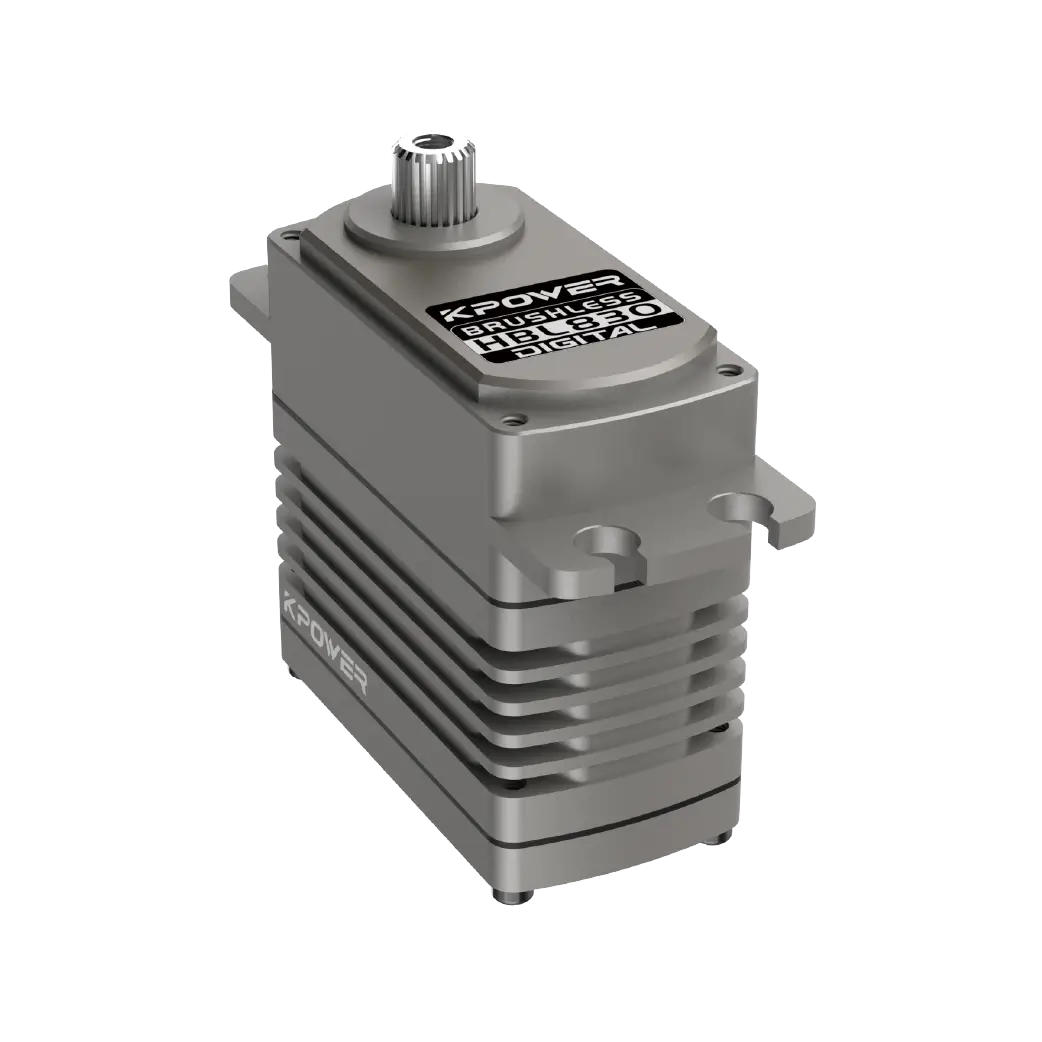
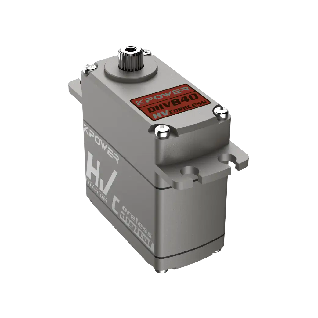
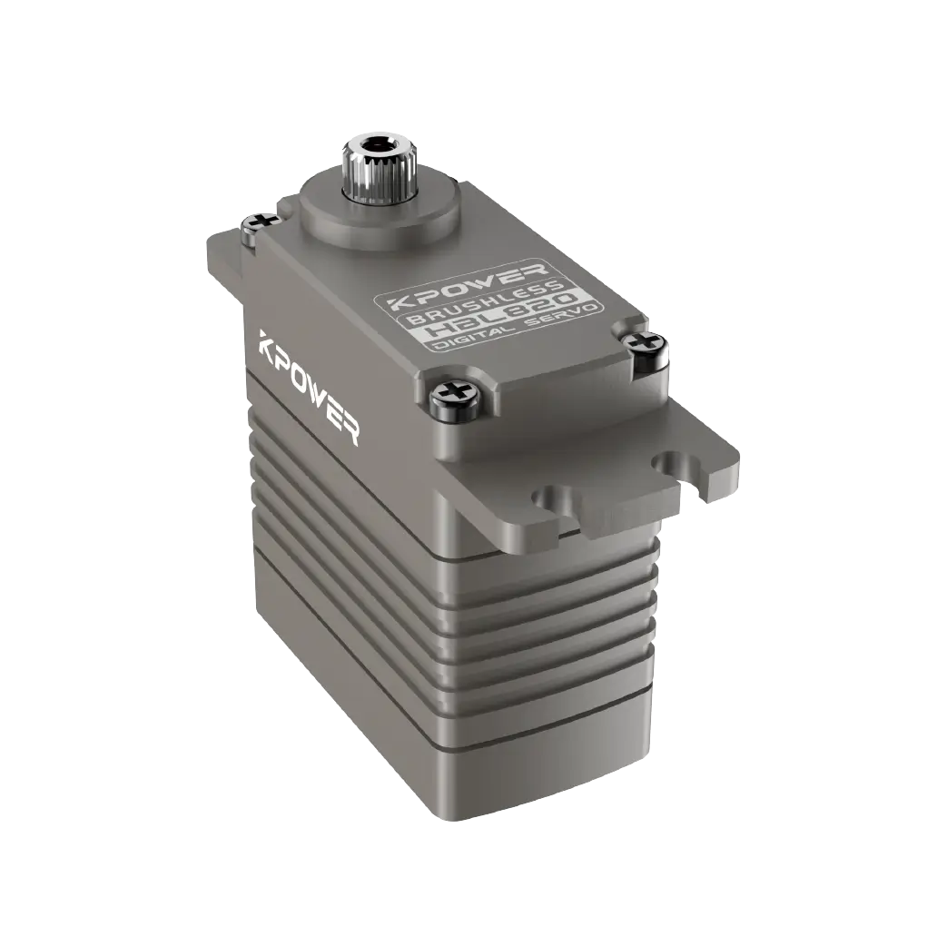
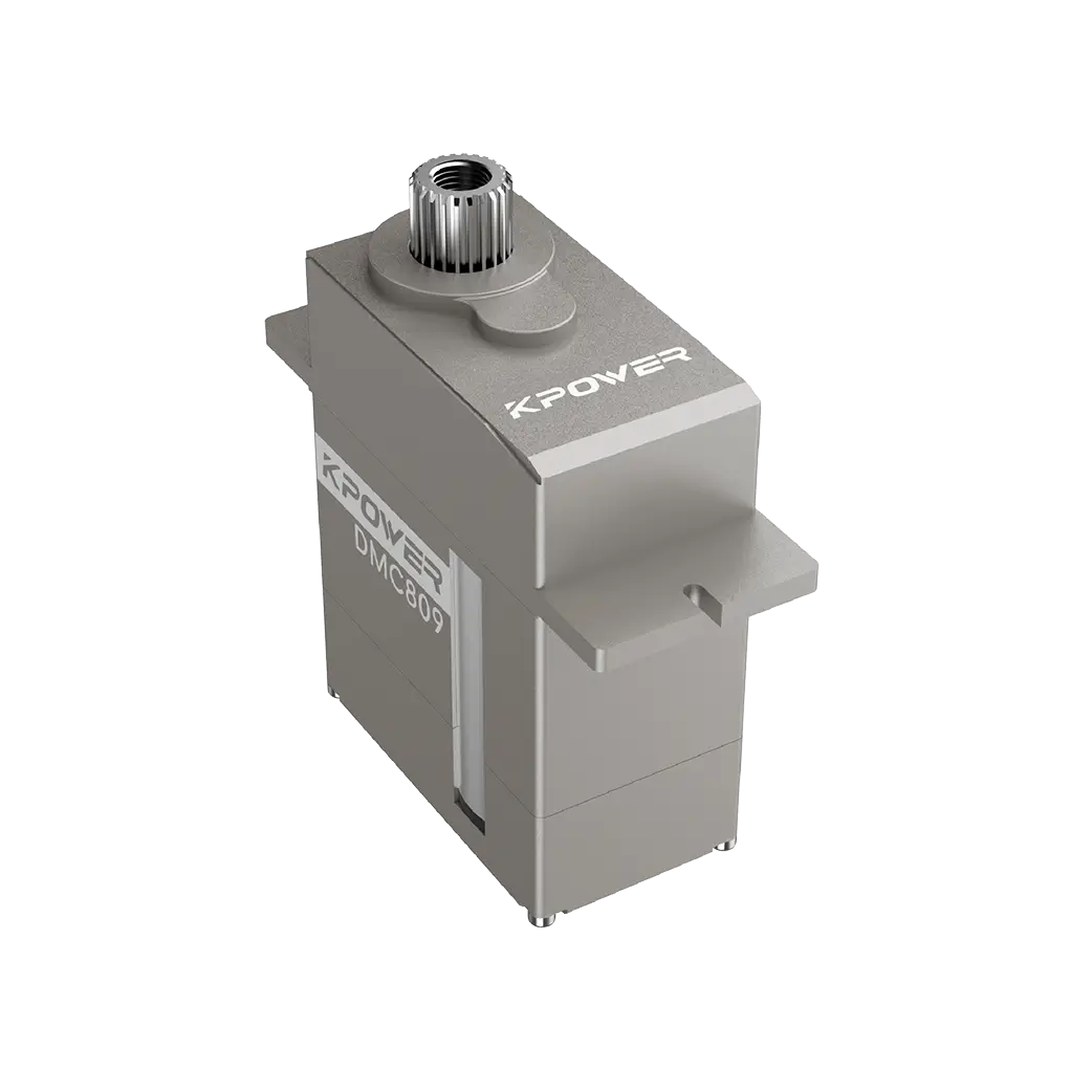
Servo motor– The actuator that rotates to a commanded angle based on PWM signal input. The output shaft connects to a servo horn.
Servo horn– An arm attached to the servo output spline. It transfers rotational motion to the linkage system.
Steering arm or bell crank– A lever that changes the direction or magnitude of force from the servo horn to the tie rod.
Those born– A rigid link that connects the steering arm to the wheel knuckle. It pushes or pulls the wheel to steer.
Knuckle or upright– The rotating assembly that holds the wheel hub and allows the wheel to pivot around a kingpin or ball joint.
Wheel hub and bearing assembly – Supports the wheel and friction reduces during steering.
Each component must be sized correctly for the vehicle weight, speed, and operating environment. A mismatch in any single part can cause sloppy steering, excessive wear, or mechanical failure.
04 How the Steering Linkage Transfers Motion
The steering linkage is the mechanical bridge between the servo and the wheels. Understanding its geometry is critical for reliable performance.
When the servo rotates clockwise, the servo horn pulls the steering arm forward. That motion travels through the tie rod to the knuckle, turning the wheel. A reverse rotation pushes the wheel the other way.
The ratio between servo rotation and wheel angle is determined by the lever arm lengths. A longer servo horn gives more wheel travel per degree of servo rotation but reduces mechanical advantage. A shorter horn increases torque at the wheel but requires more servo rotation for the same turn.
For most servo steering car structures , a 1:1 or slightly progressive ratio provides a good balance of responsiveness and torque. If the vehicle is heavy or runs at high speed, a higher mechanical advantage reduces the chance of the servo stalling during sharp turns.
One common mistake is assembling the linkage with too much slop. Ball joints or rod ends with threads allow fine adjustment of toe angle. Even 1–2 mm of play at the tie rod end translates to noticeable steering wander at higher speeds.
05Choosing the Right Servo for Your Application
Selecting the correct servo is the most important decision in building a servo steering car structure . The wrong choice leads to poor control, overheating, or mechanical damage.
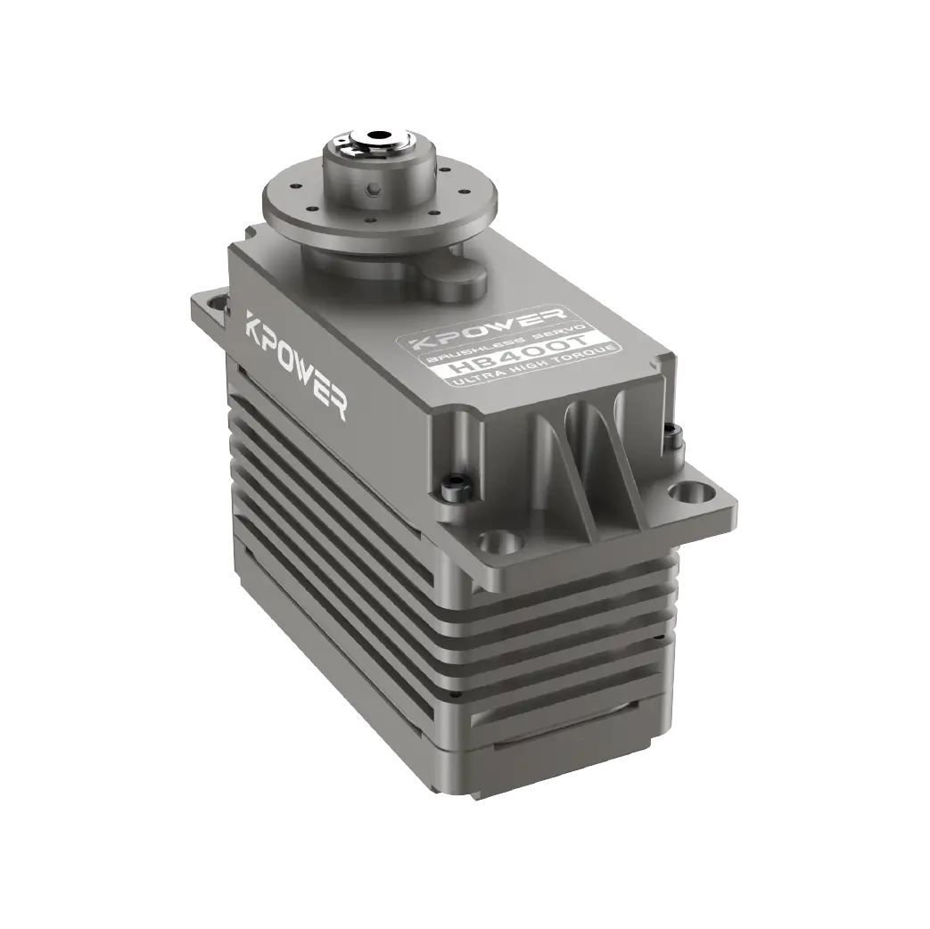
Torque rating – Measured in kg·cm or oz·in. A typical small RC car (1–2 kg) needs 3–5 kg·cm. A larger or heavier vehicle (5–10 kg) requires 8–15 kg·cm. Always select a servo with at least 20–30% headroom above your calculated requirement.
Speed – Measured in seconds per 60 degrees. Faster servos (0.08–0.12 sec/60°) improve steering response but consume more current. Slower servos (0.15–0.20 sec/60°) are adequate for most utility vehicles.
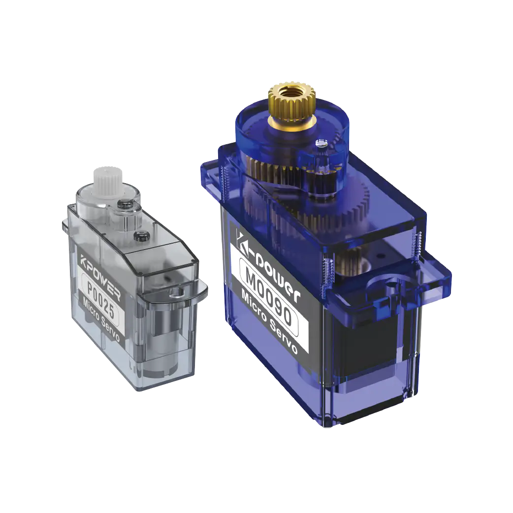
Gear material – Plastic gears are quiet and inexpensive but strip under impact. Metal gears (steel or titanium) are essential for off-road, high-speed, or heavy vehicles.
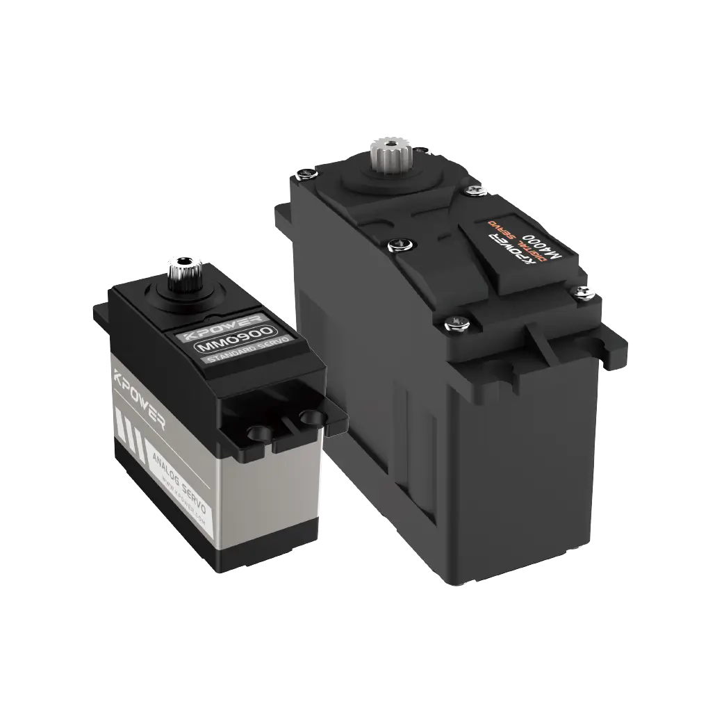
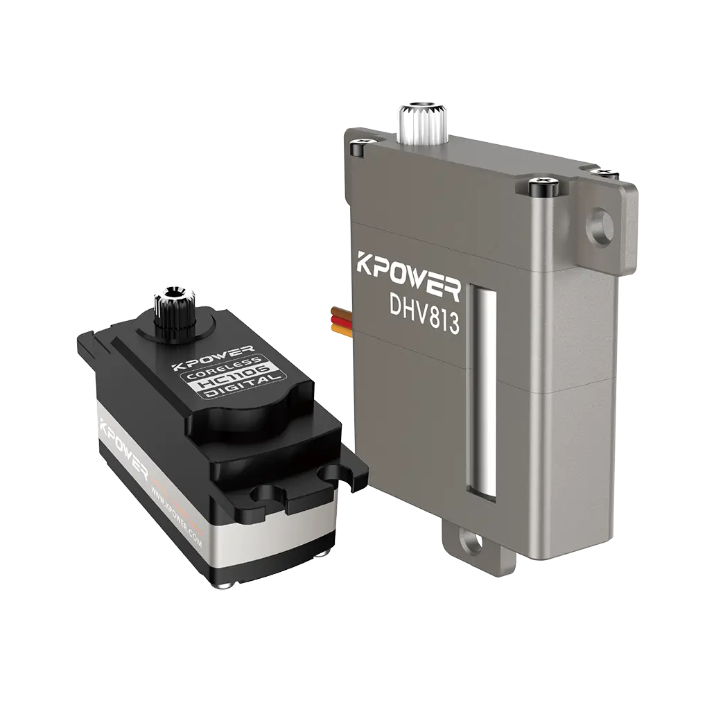
Analog vs. digital – Analog servos are simpler and cheaper but have less holding torque and can drift. Digital servos provide faster response, higher holding torque, and better precision, which matters for applications requiring consistent steering angle.
Operating voltage – Most servos run on 4.8–6.0 V. Higher voltage increases torque and speed but generates more heat. Verify your power supply and servo specifications match.
A buyer checklist can help you compare options quickly:
The layout of the servo steering car structure affects turning radius, stability, and tire wear. Three configurations are widely used.

Ackermann steering – The inner wheel turns at a sharper angle than the outer wheel, reducing tire scrub during turns. This geometry is best for vehicles that need stable cornering on paved surfaces. The servo is typically mounted centrally and connected via a drag link to both wheels.
Parallel steering – Both wheels turn at the same angle. This is simpler to build and works well for slow-speed robots or vehicles that pivot on the spot. However, tire wear increases during sharp turns.
Crab steering – All wheels turn in the same direction, allowing the vehicle to move sideways. This requires multiple servos and a more complex linkage but offers unique maneuverability for specialized applications.
For most builders, Ackermann geometry provides the best balance of stability and turning performance. If you are prototyping, start with a simple parallel setup and adjust after testing.
Before you mount the servo and connect the linkage, verify these five parameters:
Servo mounting bolt pattern and dimensions – Ensure the servo fits the bracket or chassis cutout. Standard sizes are 23×12 mm (micro), 40×20 mm (standard), and 54×30 mm (large).
Servo horn spline count and shape – Most servos use 25-tooth or 24-tooth splines, but compatibility varies. The horn must fit securely without play.
Tie rod length range – Adjustable tie rods with threaded ends allow fine toe adjustment. Minimum and maximum length should cover the required wheel angle without binding.
Wheelbase width and turning radius requirement – Narrower wheelbases need less servo torque but may be less stable at speed. Calculate the maximum turning angle needed for your operating space.
Clearance around the linkage – The steering arm and tie rod must not hit the chassis, suspension arms, or wheels at full lock. Dry cycle the system before final assembly.
Checking these items before assembly saves time and prevents rework. A few minutes of measurement can avoid hours of troubleshooting later.
Q: Can I use a standard RC servo for a 5 kg robot car?
Yes, but you will need a servo with at least 10 kg·cm torque and metal gears. Standard plastic-gear servos will strip under load. Verify the mounting bracket and power supply can handle the continuous draw.
Q: What is the difference between analog and digital servos for steering?
Digital servos update the motor control signal more frequently, providing faster response, higher holding torque, and better precision. Analog servos are less expensive but may drift or lag under load. For precision steering, digital is recommended.
Q: How do I prevent steering linkage binding?
Ensure all rod ends or ball joints move freely without forcing the servo to its mechanical stop. Use spacers or washers to align the linkage in a single plane. Test the full range of motion before applying power.
Q: What causes servo jitter in a steering system?
Jitter is often caused by insufficient power supply voltage, electrical noise from nearby motors, or a weak signal from the controller. Use a separate BEC or voltage regulator for the servo, and keep servo signal wires away from high-current power cables.
Q: How often should I replace servo gears?
Check after every 20–30 hours of operation or after any hard crash. If the servo makes grinding noises, loses centering accuracy, or has visible play, replace the gear set immediately to prevent further damage.
Q: Is waterproofing necessary for a servo steering car structure?
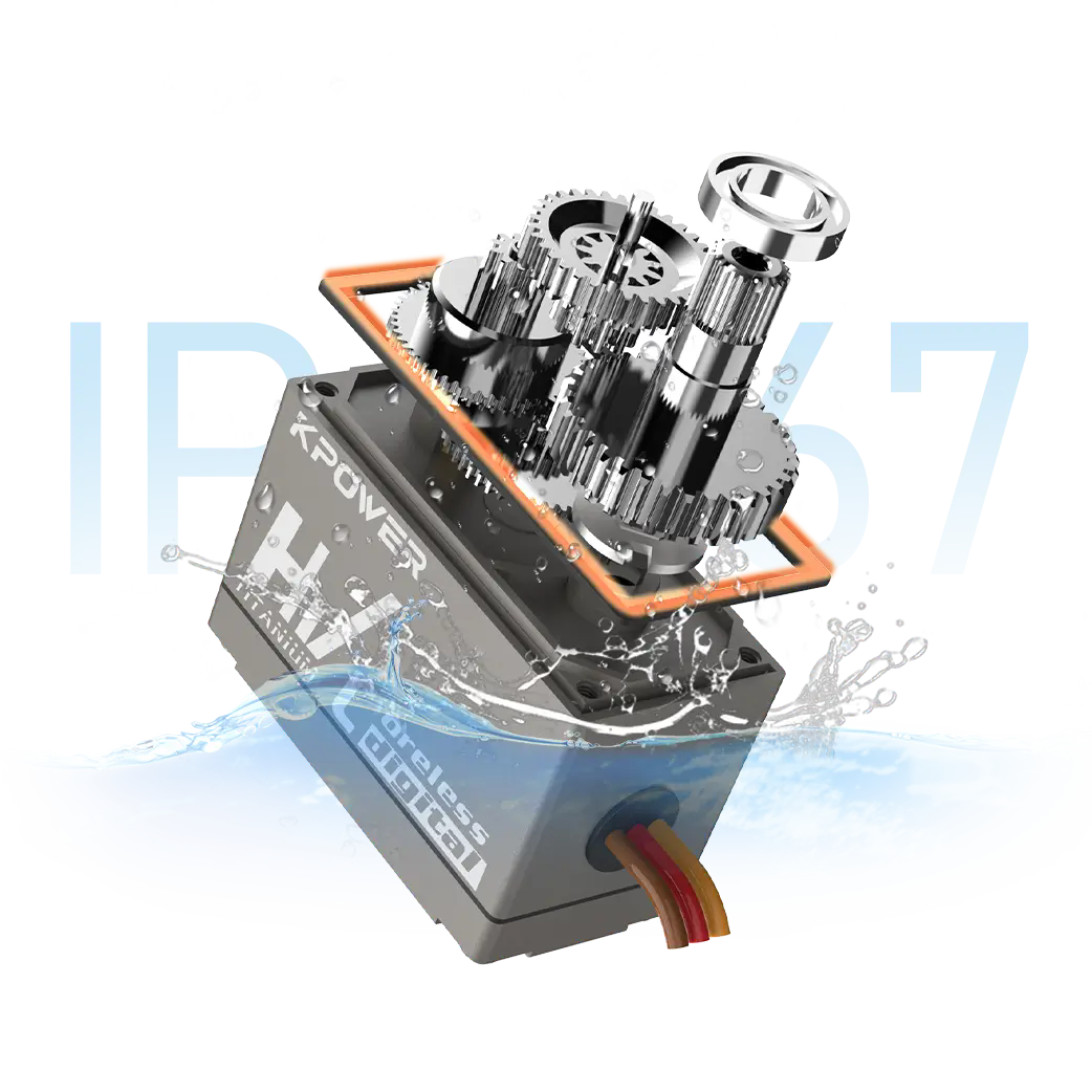
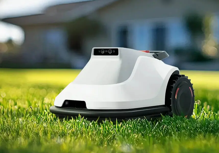
Not always, but if you operate on wet grass, mud, or near water, choose a servo with an IP rating of at least IP67. Standard servos can fail quickly if moisture enters the gear train or electronics.
Q: What happens if the servo torque is too low?
The servo may stall during turns, causing the vehicle to understeer or stop responding. In extreme cases, the servo motor can overheat and fail permanently. Always calculate torque requirements with a safety margin.
Q: Can I use one servo to steer two wheels?
Yes. A single servo connected via a drag link or tie rod to both wheels is a common design. The servo must be centered and the linkage symmetric to ensure equal turning in both directions.
Q: Does servo speed matter for steering accuracy?
Yes, but only up to a point. Faster servos reduce lag between command and wheel movement, which helps at high speeds. For slow-moving robots or utility vehicles, speed is less critical than torque and holding strength.
Q: How do I set the servo center position?
Send a 1500 µs PWM signal (typical center) and mount the servo horn perpendicular to the linkage. Adjust the tie rod length until both wheels point straight ahead. Fine-tune using the transmitter trim if needed.
Building a reliable servo steering car structure comes down to understanding the mechanical relationship between each component. A well-matched servo, properly aligned linkage, and correct geometry give you consistent steering performance without constant adjustments or failures.
Start by calculating your vehicle weight and operating speed. Choose a servo with sufficient torque headroom, metal gears if impact is likely, and digital control if precision matters. Verify the linkage geometry before final assembly, and test the full steering range under load.
If you are evaluating multiple servo options or need help matching components to your specific application, contact our engineering team with your vehicle specifications. We can recommend compatible parts and help you avoid common design pitfalls.
Update Time:2026-07-11

Contact Kpower's product specialist to recommend suitable motor or gearbox for your product.


