


TECHNICAL SUPPORT


Published 2026-07-05
How a BusservoInterface Controls a PWMservo
Quick Answer
A busservointerface allows a single control line to send digital commands to multiple servos, while a standard PWM servo requires a dedicated signal wire per channel. The interface converts bus-protocol commands into precise PWM pulses that standard servos can interpret. This approach reduces wiring complexity, simplifies controller requirements, and enables more scalable motion control in industrial automation. However, not all bus interfaces are compatible with every PWM servo. You must verify protocol support, voltage levels, and timing resolution before integration.
Introduction
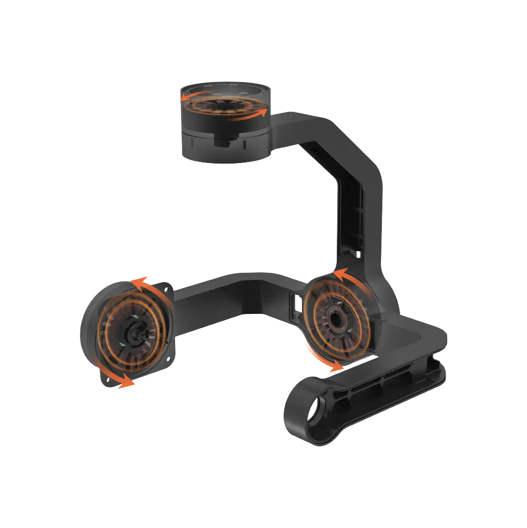
Every production line manager has faced the same frustration: a multi-axis motion system that requires a separate wire for every servo. The cable bundles grow thicker, troubleshooting becomes slower, and adding one more axis means rewiring the entire cabinet. The solution is a bus servo interface that translates a single digital signal into multiple PWM outputs. But the real question is not whether it works. It is whether the interface actually maintains the precision, timing, and reliability your application requires. Many buyers adopt this technology only to discover signal latency, jitter, or protocol mismatches that degrade performance. Understanding how the interface works—and where it fails—is the difference between a scalable system and a costly mistake.
Table of Contents
1. What is a Bus Servo Interface?
2. How the Bus-to-PWM Conversion Works
3. Key Parameters That Affect Performance
4. Common Integration Mistakes and How to Avoid Them
5. What to Check Before Choosing a Bus Servo Interface
6. Questions Buyers Often Ask About Bus-to-PWM Control
7. Choosing the Right Interface for Your Application
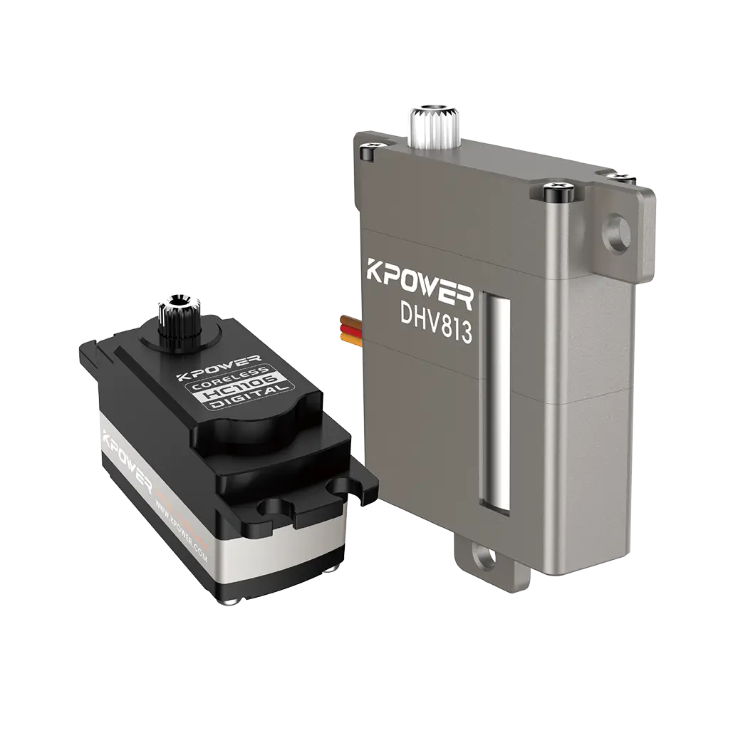
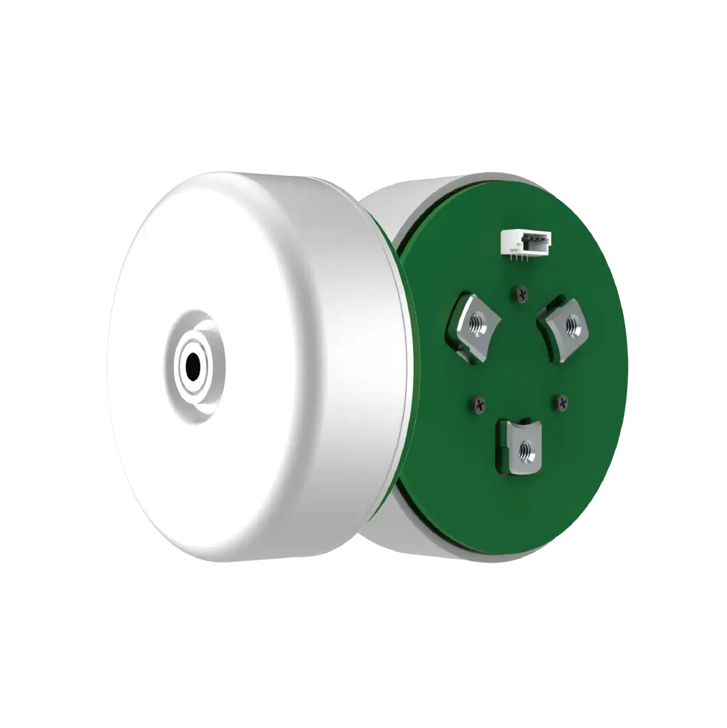
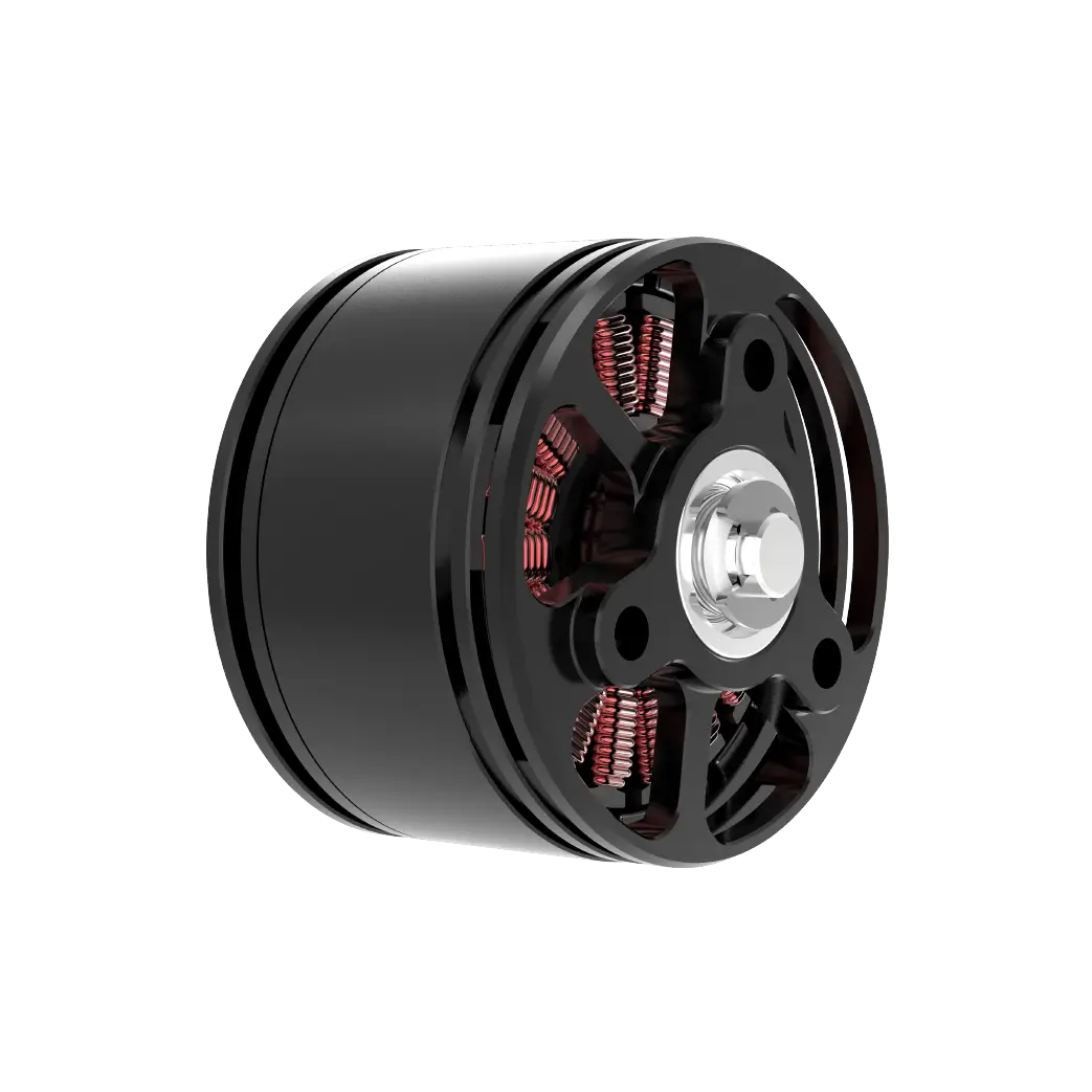
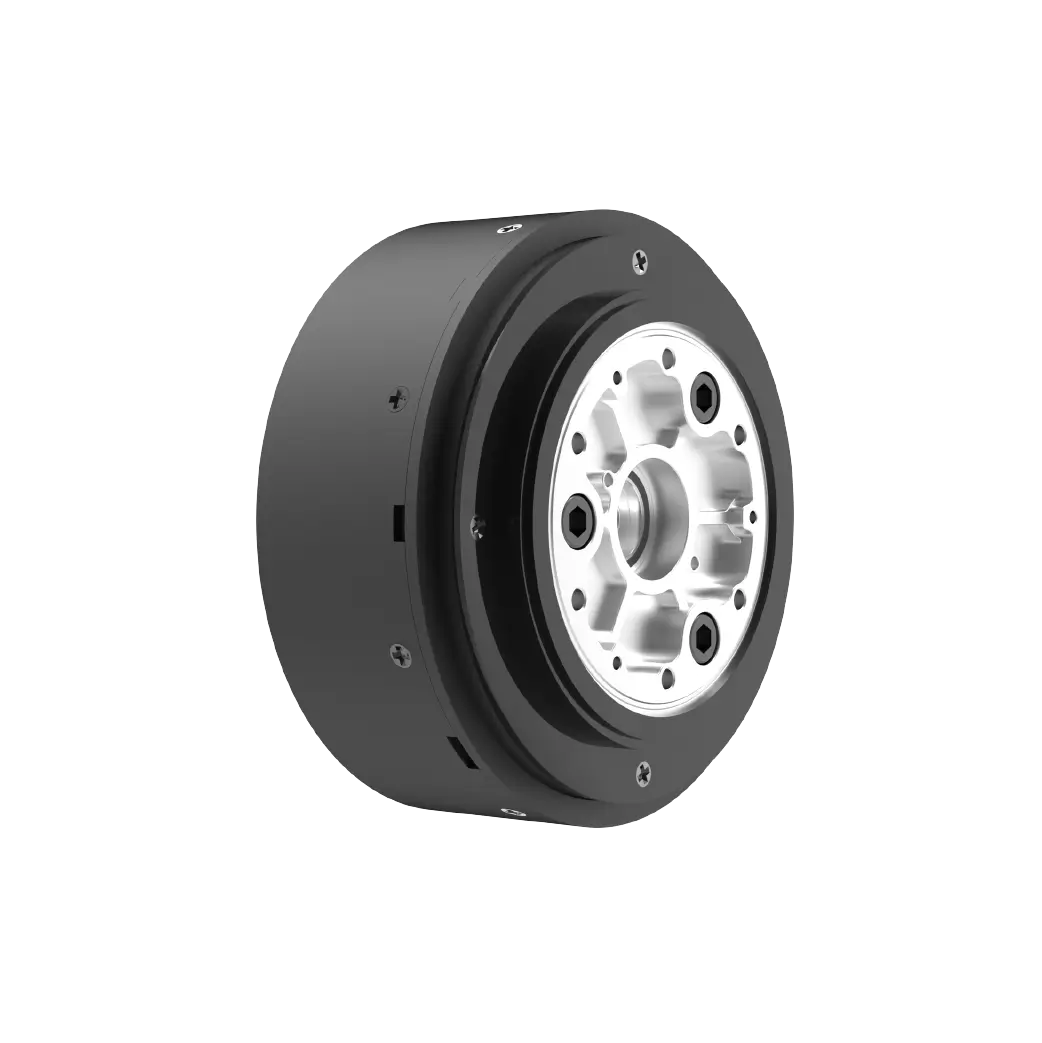
1. What is a Bus Servo Interface?
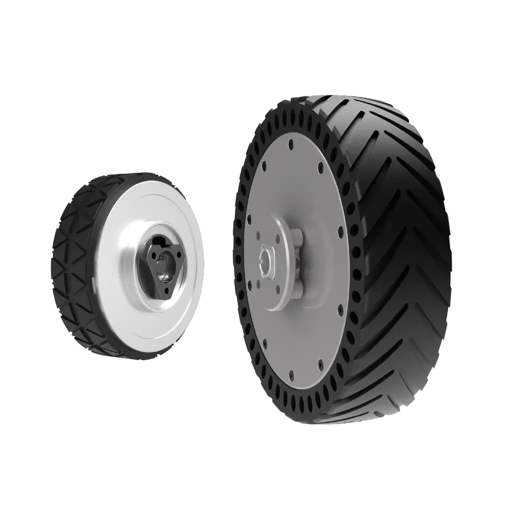
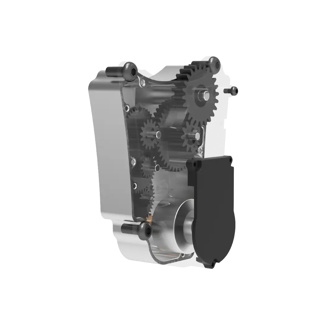
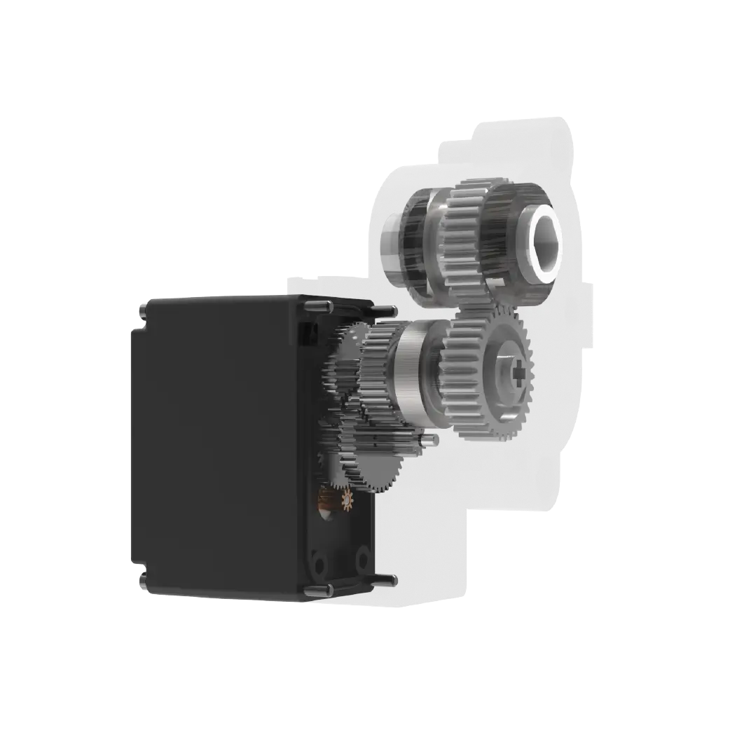
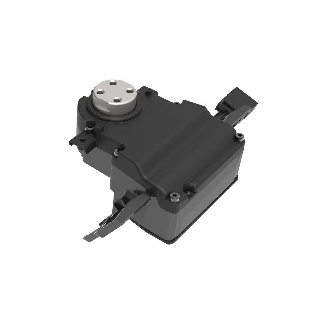
A bus servo interface is a hardware module or embedded controller that receives digital commands over a shared communication bus—such as RS485, CANopen, or EtherCAT—and converts them into standard PWM signals that conventional servos can read. In a typical PWM system, each servo requires its own signal wire connected to a dedicated controller channel. As axis count increases, so does wiring cost, cabinet space, and failure risk. A bus interface collapses this complexity into a single cable running from the chain to a daisy-ed controller series of interface modules, each driving one or more PWM servos. The benefit is obvious: less wiring, faster installation, and easier maintenance. But the trade-off is that the conversion from bus protocol to PWM timing must be precise enough to avoid position error, signal drift, or command delay.
2. How the Bus-to-PWM Conversion Works
The conversion process follows three steps. First, the interface receives a digital frame from the bus. This frame contains an address, a target position or speed value, and sometimes a checksum for error detection. Second, the interface decodes the frame and extracts the command value. Third, it generates a corresponding PWM pulse with a specific on-time duration—typically between 1.0 ms and 2.0 ms for a 0-to-180-degree rotation range. The pulse is repeated every 20 ms, which is the standard PWM refresh rate for most hobby and industrial servos.
The accuracy of this conversion on the interface's timing resolution. A low-cost interface might use a software timer that introduces jitter of 50 µs or more, which translates to several degrees of position error. A professional-grade interface uses a hardware timer or dedicated PWM generator with microsecond-level precision. If your application requires repeatable positioning within 0.5 degrees, you must verify that the interface can maintain a timing resolution of at least 1 µs.
3. Key Parameters That Affect Performance
Not all bus servo interfaces perform equally. The following parameters directly influence whether your system will operate reliably or produce inconsistent motion.
Timing resolutiondetermines how finely the interface can adjust pulse width. A resolution of 1 µs allows 1000 discrete position steps within the 1.0-to-2.0 ms range. A resolution of 10 µs reduces that to 100 steps, which may cause visible stepping or vibration.
Bus cycle timeis the interval at which the controller sends new commands. If the bus cycle is 10 ms but the PWM refresh is 20 ms, the servo may see outdated or conflicting pulses. The interface must buffer and synchronize incoming commands with the PWM output cycle.
Signal voltage and currentmust match the servo's input specification. Many PWM servos expect a 5V logic-level signal. If the interface outputs 3.3V, the servo may not recognize the pulse, causing erratic behavior or no response at all.
Error handlingvaries between interfaces. Some simply discard corrupted frames; others hold the last valid command or enter a safe state. In a production environment, a missing command can cause a servo to stop mid-cycle, creating jams or safety hazards.
4. Common Integration Mistakes and How to Avoid Them

One frequent mistake is assuming that every bus servo interface is compatible with any PWM servo. In reality, servo manufacturers often implement non-standard pulse width ranges. A servo that expects a 0.5-to-2.5 ms pulse will not respond correctly to a 1.0-to-2.0 ms output. Always check the servo datasheet and configure the interface accordingly.
Another error is ignoring the cumulative delay in a daisy-chain configuration. Each interface module adds a small processing delay. In a chain of ten modules, the total latency may exceed 50 ms, which is unacceptable for synchronized multi-axis motion. Use a bus topology with faster response times or limit the chain length based on your application's timing tolerance.
A third mistake is neglecting signal integrity. Long bus cables without proper termination can cause reflections, data corruption, and intermittent servo faults. Install terminating resistors at both ends of the bus line and use shielded twisted-pair cable for RS485 or CANopen networks.
5. What to Check Before Choosing a Bus Servo Interface
Use the following checklist when evaluating a bus servo interface for your application.
Request these specifications in writing from the supplier. If the response is vague, consider that a red flag.
6. Questions Buyers Often Ask About Bus-to-PWM Control
Can I mix bus servo interfaces from different brands in one system?
Not recommended. Protocol timing, voltage levels, and error handling differ between brands. Mixing them often leads to unpredictable behavior and difficult troubleshooting.
Does a bus interface reduce servo positioning accuracy?
It can, if the interface has low timing resolution or high jitter. A well-designed interface with hardware timing does not degrade accuracy beyond the servo's own mechanical tolerance.
How many PWM servos can one bus line support?
It depends on the bus protocol and interface design. RS485 can typically support 32 nodes per segment. CANopen supports up to 127 nodes. EtherCAT supports many more, but practical limits are set by cable length and cycle time.
What happens if the bus cable breaks?
All downstream interfaces lose communication. Some hold the last valid command; others enter a safe state. Design the system so that a single cable fault does not cause uncontrolled motion.
Is a bus interface more expensive than a dedicated PWM controller?
The interface module itself costs more per channel, but total system cost is often lower due to reduced wiring, smaller cabinets, and faster installation.
Can I retrofit an existing PWM servo system with a bus interface?
Yes, if the interface outputs the correct pulse range and voltage. Retrofitting is common when upgrading from a simple PLC to a centralized motion controller.
7. Choosing the Right Interface for Your Application
If your motion system has more than four axes, operates in a space-constrained cabinet, or requires frequent reconfiguration, a bus servo interface is likely the better choice. It reduces installation time, simplifies maintenance, and scales more cleanly than point-to-point PWM wiring.
But if your application demands microsecond-level synchronization across dozens of axes, a dedicated digital servo drive with native bus support may outperform a bus-to-PWM conversion. The interface adds one extra layer of processing that, while small, may accumulate in high-speed or high-precision lines.
Before making a decision, test the interface with your actual servo model under realistic load conditions. Measure pulse width stability, response delay, and error recovery behavior. A supplier that offers engineering support for integration testing is worth more than one that only ships boxes.
If you are evaluating a bus servo interface for your next automation project, send your servo specifications and bus protocol requirements to the kpower Servo engineering team. They can review compatibility and recommend a configuration that matches your production environment.
Update Time:2026-07-05
Contact Kpower's product specialist to recommend suitable motor or gearbox for your product.


