


TECHNICAL SUPPORT


Published 2026-07-05
Quick Answer
Helicopter pedal control, also known as anti-torque pedal input, directly manages the pitch angle of the tail rotor blades to counteract the main rotor torque and control yaw. Proper pedal response depends on theservosystem's precision, the tail rotor's mechanical condition, and the control loop's calibration. For operators and maintenance teams, degraded pedal feel or delayed yaw correction often indicates a failing actuator, hydraulic leak, or electrical feedback issue. Addressing these early prevents loss of directional control during hover and low-speed flight.
Introduction
Every helicopter pilot knows the moment when the pedals feel wrong. The aircraft drifts left during a hover. The nose swings unpredictably during a crosswind approach. The corrective input you apply doesn't produce the expected yaw response. For maintenance managers, production supervisors, and procurement engineers, these symptoms translate into grounded aircraft, extended downtime, and escalating repair costs. safety margins shrink and operational efficiency drops. Understanding how pedal control works, what degrades its performance, and how to evaluate replacement components becomes a critical competency for anyone responsible for fleet reliability.
Table of Contents
How Helicopter Pedal Control Works
Why Yaw Response Degrades Over Time
What Affects Pedal Precision and Feel
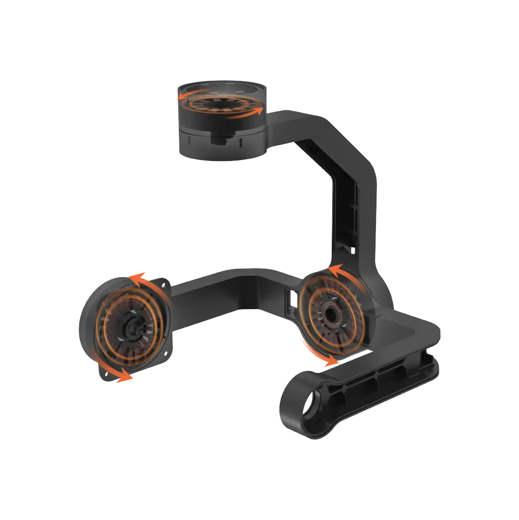
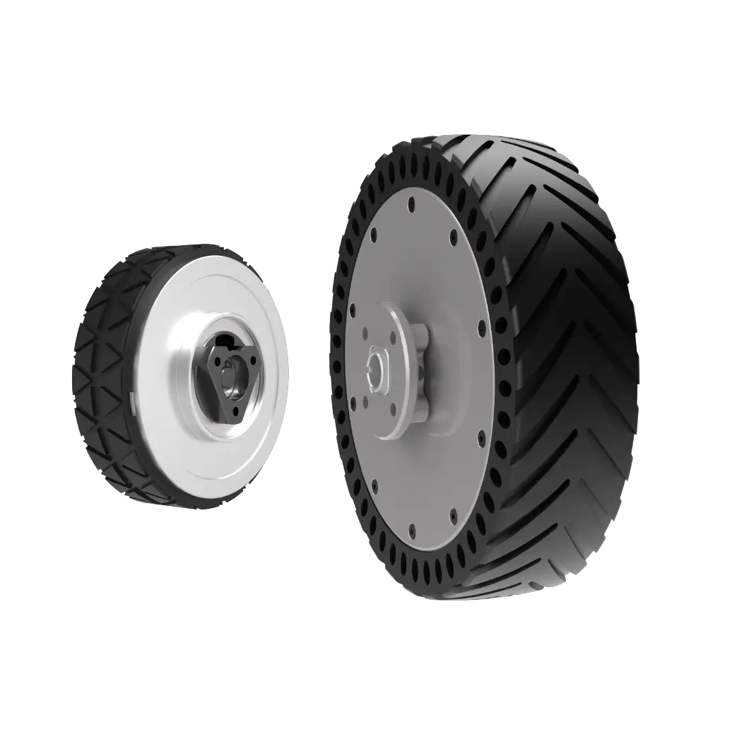
Key Components in the Pedal-to-Rotor Chain
How to Diagnose Pedal Response Problems
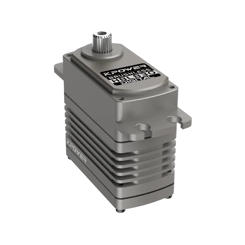
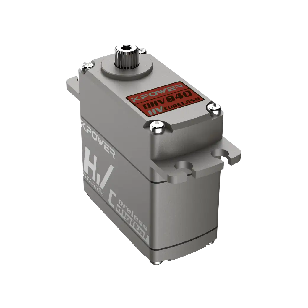
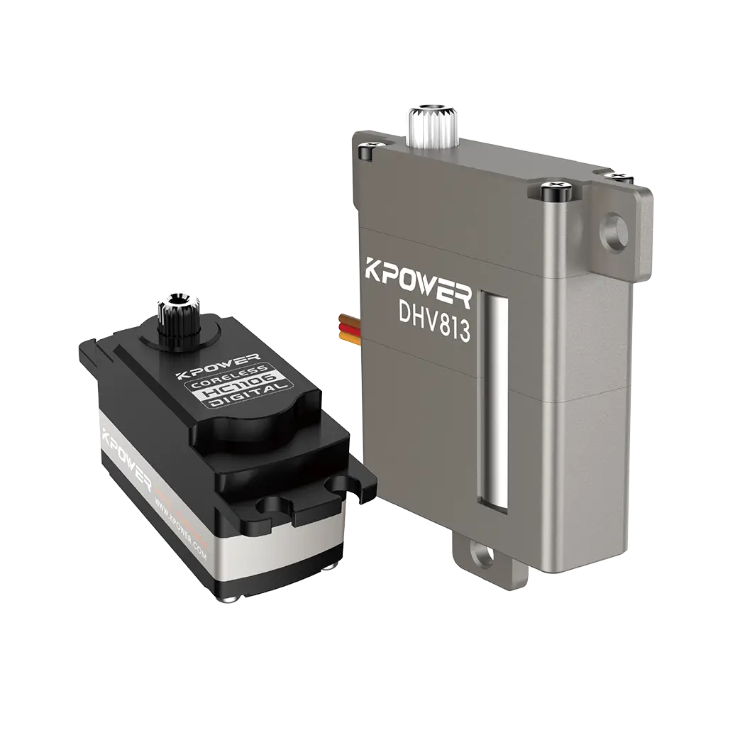
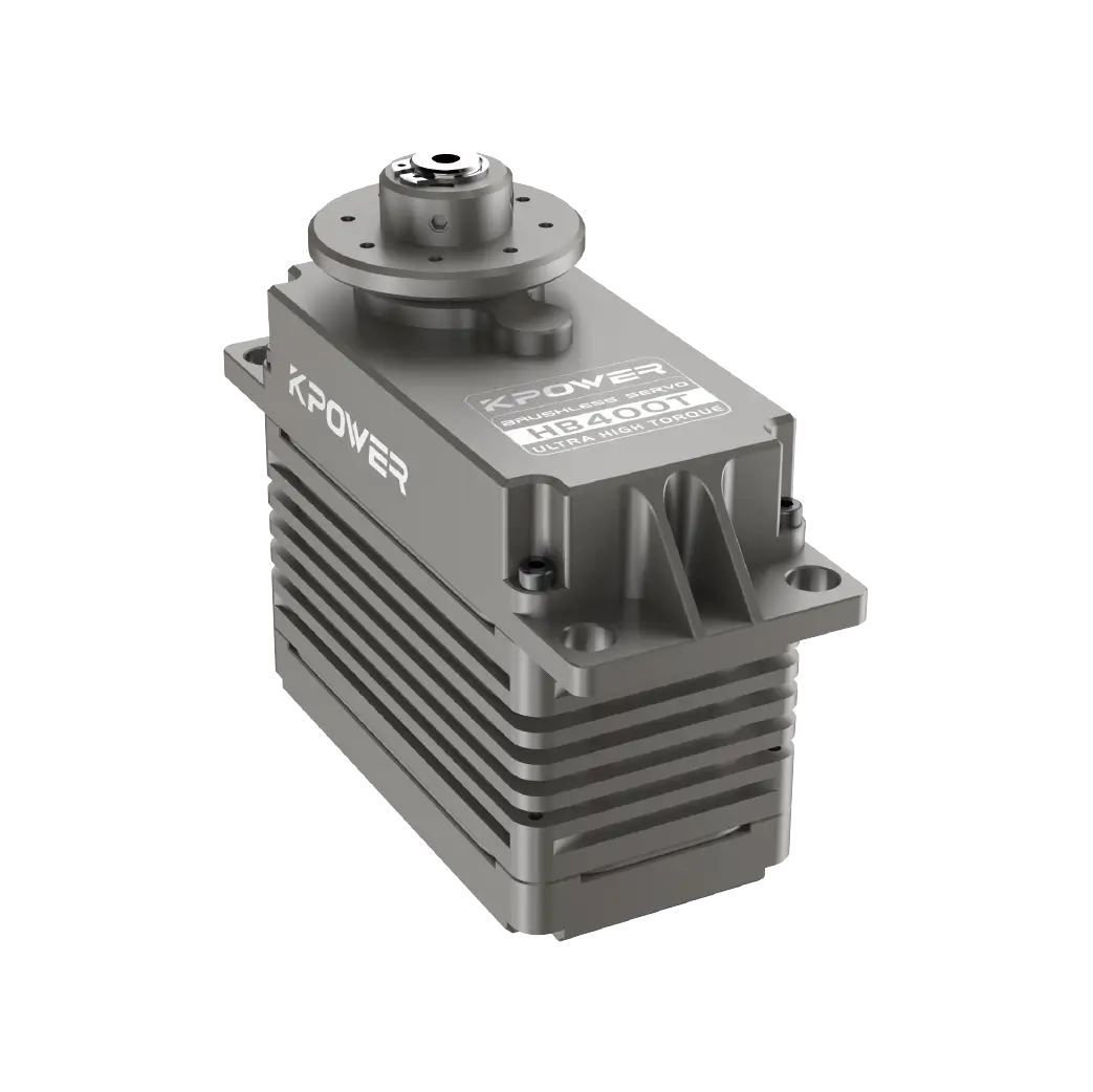
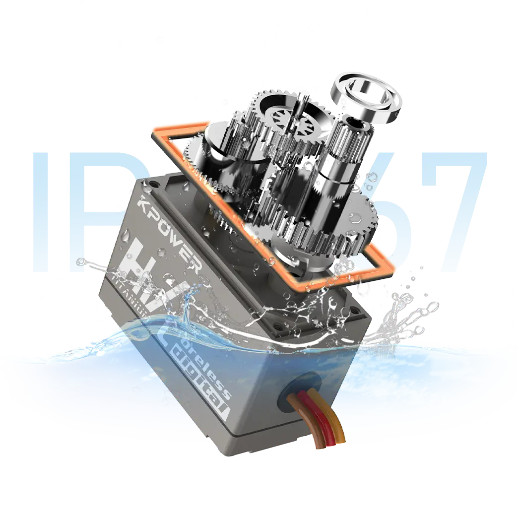
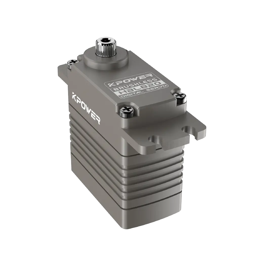
Selection Guide for Replacement Actuators andservos
Common Questions About Helicopter Pedal Control
Choosing the Right Solution for Your Fleet
How Helicopter Pedal Control Works
The pedals in a helicopter cockpit do not directly move the tail rotor blades. Instead, they transmit a mechanical or electrical command through a control chain that includes push-pull tubes, cables, hydraulic boost actuators, or electricservos. The final link in that chain adjusts the pitch angle of the tail rotor blades, which changes the amount of thrust produced to counter the main rotor torque.
In modern helicopters, the pedal input is often processed by aflight control computerthat compares the pilot's command against sensor feedback from the tail rotor pitch link and the yaw rate gyro. The computer then commands an actuator—either hydraulic or electric—to move the blades to the correct angle. This closed-loop system allows for fine adjustments that a purely mechanical linkage cannot achieve. However, it also introduces failure points: sensor drift, actuator lag, electrical noise, and software calibration errors.
For a procurement professional evaluating replacement components, the key parameter is not just whether the actuator moves, but how precisely it follows the command signal under varying load conditions. A servo that exhibits hysteresis or deadband will cause the pilot to overcorrect, leading to a fatiguing flight experience and increased wear on the entire tail rotor assembly.
Why Yaw Response Degrades Over Time
Three main factors cause pedal response to deteriorate: mechanical wear, hydraulic contamination, and electronic degradation. Mechanical wear manifests in the pitch link bearings, the actuator rod ends, and the torque tube splines. As clearances increase, the pilot's input must travel further before the blades begin to move. This creates a dead zone in the pedal travel, often described as "sloppy" pedals.
Hydraulic contamination, particularly in systems using MIL-PRF-83282 or similar fluids, can cause valve spools to stick or slow down. When a hydraulic actuator responds sluggishly, the tail rotor pitch change lags behind the pedal input. At low rotor RPM or during hover, this delay can be enough to require constant corrective cycling, which accelerates actuator seal wear.
Electronic degradation affects fly-by-wire systems. Potentiometers and LVDTs (linear variable differential transformers) used in pedal position sensors and feedback loops drift over time due to temperature cycling and vibration. A sensor that reports 2% error at neutral may cause the flight control computer to hold the tail rotor at a slight positive or negative pitch, forcing the pilot to hold steady pressure on the pedals. That constant pressure leads to leg fatigue and reduces the pilot's ability to manage other flight tasks.
What Affects Pedal Precision and Feel
Pedal precision is determined by the combined resolution of every component in the control chain. The servo actuator's internal friction, the backlash in the mechanical linkage, and the update rate of the digital controller all contribute. For helicopters that operate in high-vibration environments—such as agricultural spraying, external lift, or maritime patrol—the degradation rate accelerates.
Temperature also plays a significant role. Hydraulic fluid viscosity changes with temperature, affecting actuator response time. Electric servos, particularly those using brushed DC motors, lose torque as internal resistance increases with heat. In hot climates, a servo that passed bench testing at 20°C may show noticeable lag after one hour of flight at 45°C ambient temperature.
The type of tail rotor design matters as well. Helicopters with aa window or ducted tail rotor typically require different actuator response characteristics than those with an open tail rotor. The aerodynamic loading on the blades changes with airspeed and collective pitch, and the actuator must be capable of holding position against that load without drifting. A servo that cannot hold its commanded position under aerodynamic load will cause the helicopter to yaw unexpectedly during power changes.
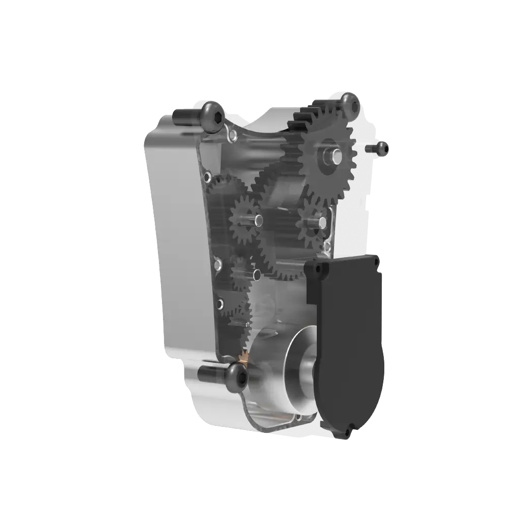
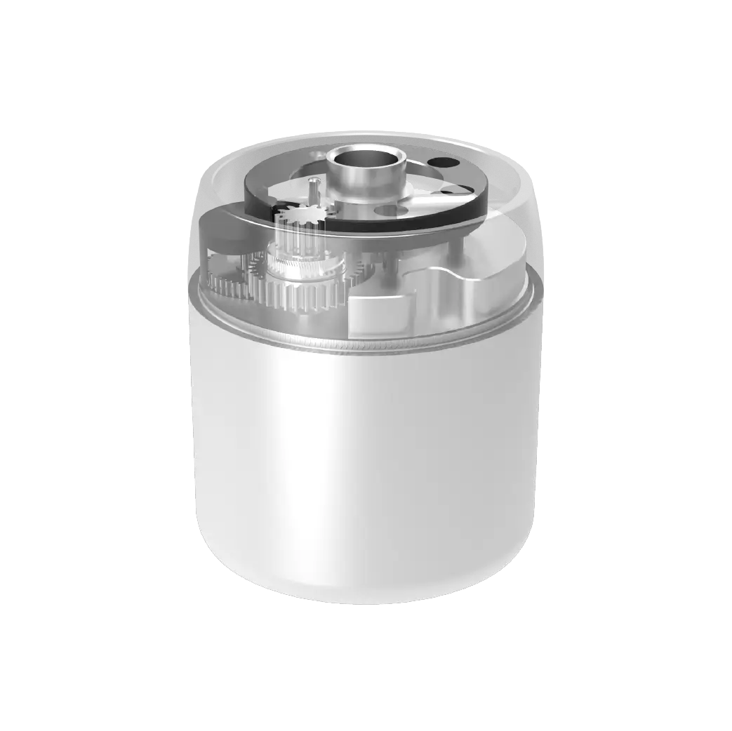
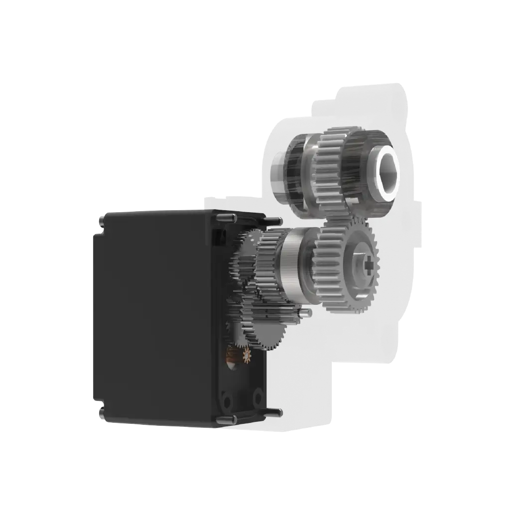
Key Components in the Pedal-to-Rotor Chain
To evaluate pedal control performance, you need to inspect or specify the following components:
Pedal position sensor – Converts mechanical pedal movement into an electrical signal. Resolution and linearity determine how accurately the system reads pilot input.
Flight control computer – Processes the command signal and applies control laws. The update rate and filtering algorithms affect response smoothness.
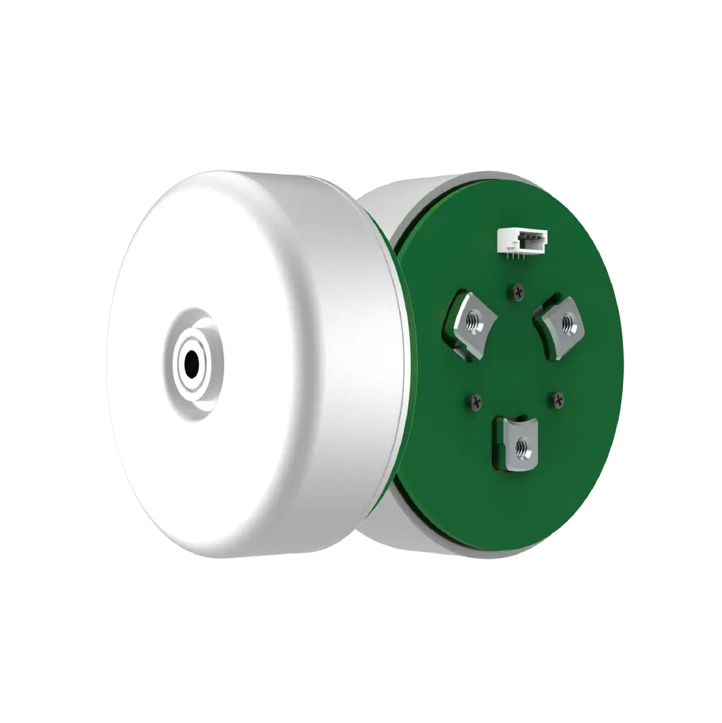
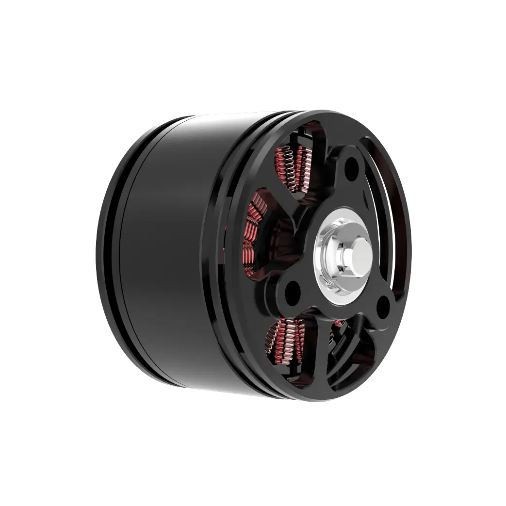
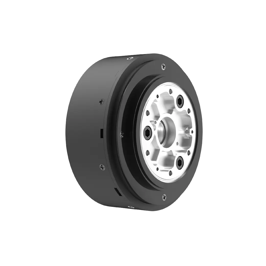
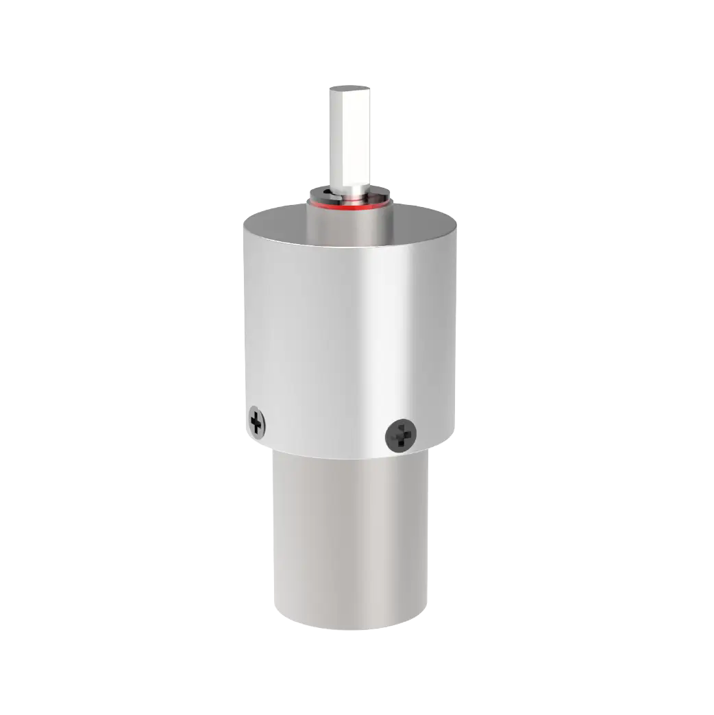
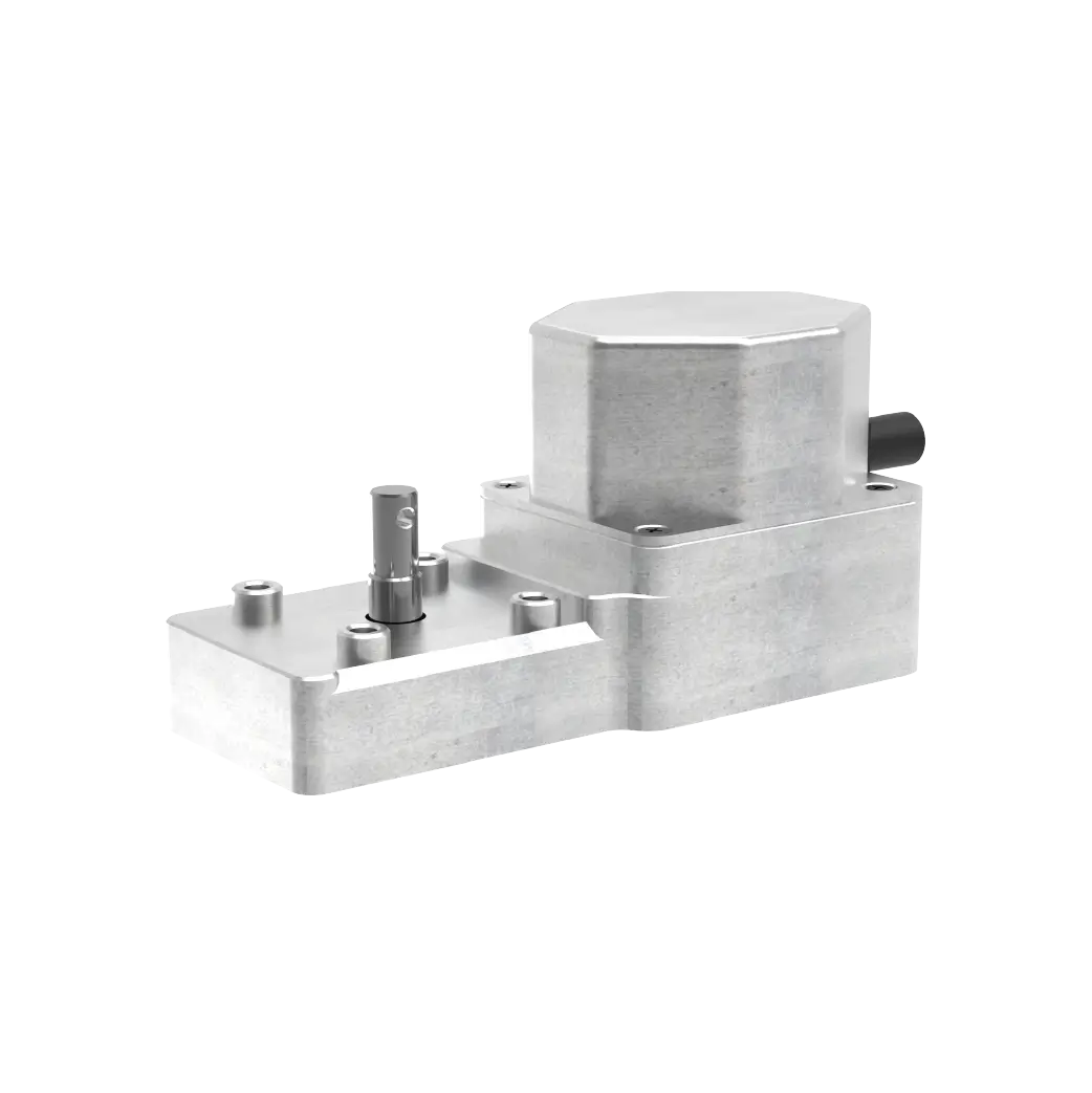
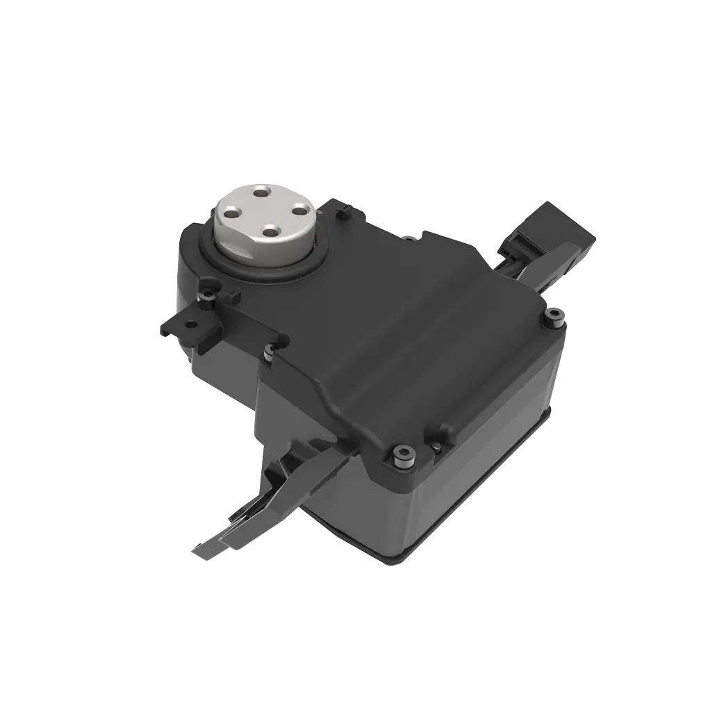
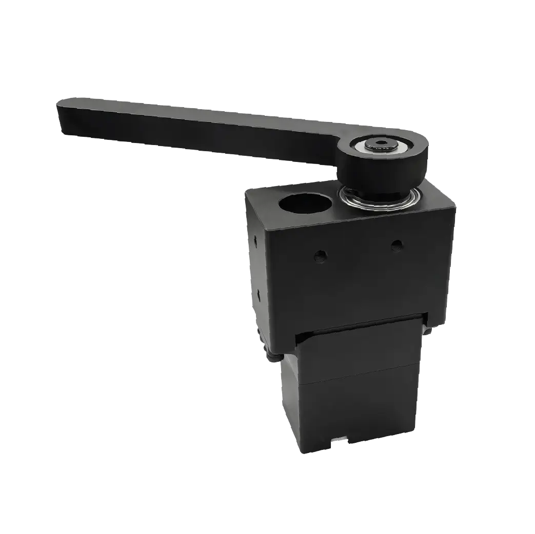
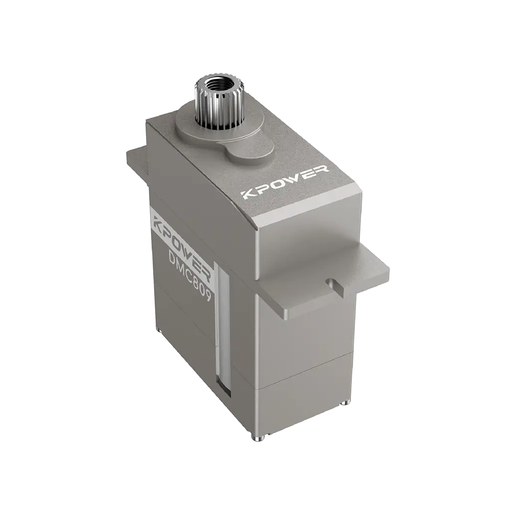
Actuator (hydraulic or electric) – Converts the command into mechanical motion. Stall torque, slew rate, and position hold accuracy are critical specifications.
Pitch link and bellcrank assembly – Transfers actuator motion to the blade grips. Bearing condition and lubrication schedule determine long-term precision.
Feedback sensor – Reports actual blade pitch position back to the control computer. Drift in this sensor creates a false error signal, causing the actuator to hunt.
Hydraulic supply – For hydraulic actuators, system pressure, flow rate, and fluid cleanliness directly affect response time and holding force.
When sourcing replacement components, request the following data from suppliers: actuator hysteresis percentage, maximum deadband, step response time, and temperature range rating. This information allows you to compare options on a performance basis rather than price alone.
How to Diagnose Pedal Response Problems
Before replacing any component, perform a structured diagnostic sequence. Start with a ground test: cycle the pedals through full travel while listening for binding or uneven resistance. Measure the force required to move the pedals at each point in the travel. An increase above specification indicates mechanical binding in the linkage or actuator.
Next, check the feedback loop. With the hydraulics or electrical power applied, hold the pedals at a fixed position and observe the tail rotor pitch. If the pitch drifts without pedal movement, the actuator is not holding position. This could be caused by internal leakage in a hydraulic actuator, or by a failing brake in an electric servo.
Perform a step response test. Command a small pedal input—approximately 10% of travel—and measure how long it takes for the tail rotor pitch to stabilize. A response that overshoots and then oscillates indicates low damping in the control loop or excessive friction. A response that slowly ramps to the final position suggests hydraulic flow restriction or motor torque deficiency.
Finally, review maintenance logs for previous actuator replacements, hydraulic filter changes, and control system software updates. Recurring issues with the same tail number often point to an underlying problem such as wiring chafing, connector corrosion, or a misconfigured flight control computer.
Selection Guide for Replacement Actuators and Servos
Use this table as a baseline when evaluating quotes from different suppliers. A servo that meets or exceeds these parameters will likely deliver consistent pedal response over its service life. A servo that falls short on slew rate or hysteresis will produce a noticeable degradation in yaw control, especially during low-speed maneuvering.
Common Questions About Helicopter Pedal Control
Q: Why do my pedals feel stiff after a hydraulic component replacement?
Stiff pedals often indicate air in the hydraulic system or incorrect actuator alignment. Cycle the system through full travel several times on the ground to purge trapped air. If stiffness persists, check the actuator mounting angles for binding.
Q: Can a servo actuator cause a yaw oscillation?
Yes. A servo with excessive gain or insufficient damping will overshoot the commanded position and then correct back, creating a continuous oscillation. This typically requires a control loop gain adjustment or servo replacement.
Q: How often should pedal position sensors be calibrated?
Most manufacturers recommend calibration every 12 months or 1,000 flight hours, whichever comes first. Calibration ensures the full pedal travel range corresponds correctly to the commanded blade pitch angle.
Q: What is the most common cause of uncommanded yaw?
The most common cause is a failing feedback sensor that reports an incorrect blade pitch position to the flight control computer. The computer then commands an incorrect actuator position to compensate for the false reading.
Q: Does pedal response change with altitude?
Yes. As air density decreases, the tail rotor produces less thrust for the same blade pitch angle. The flight control computer should compensate automatically, but if the actuator cannot hold position at lower density altitudes, you may experience reduced yaw authority.
Q: Can upgrading to a digital servo improve pedal feel?
In many cases, yes. Digital servos offer higher update rates and better position holding than analog servos. However, compatibility with the flight control computer must be verified before installation.
Q: What should I check if the pedals are hard to move on the ground but normal in flight?
This indicates a mechanical binding issue that is masked by aerodynamic forces in flight. Inspect the push-pull tube bearings, bellcrank pivots, and actuator rod end bearings for corrosion or contamination.
Q: How do I know if my tail rotor actuator is nearing end of life?
Monitor for increasing deadband, slower step response, and higher than normal current draw. Compare current performance against baseline measurements recorded after the last replacement. A 20% degradation is a reliable indicator to schedule replacement.
Choosing the Right Solution for Your Fleet
Pedal control is not a single-component problem. It is a system-level performance issue that spans sensors, computers, actuators, and mechanical linkages. When you evaluate replacement components, you are not just buying a part—you are investing in flight safety, pilot comfort, and fleet availability.
Focus on specifications that directly affect yaw response: hysteresis, slew rate, temperature range, and feedback redundancy. Compare supplier documentation against your helicopter's operational profile. A servo that works well for a training helicopter may not be adequate for an external lift or maritime patrol aircraft.
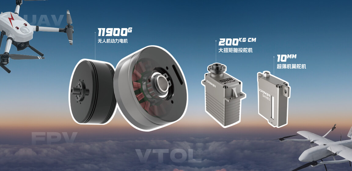
Work with a supplier that provides detailed technical data sheets, application engineering support, and documentation compatible with your maintenance tracking system. If you are evaluating kpowerservo or similar motion control solutions, request performance data under your specific load and temperature conditions. A component that has been validated in a representative environment will reduce the risk of field failures and unscheduled grounding.
Review your current fleet's pedal response performance data. Identify the tail numbers with the highest number of control system write-ups. Cross-reference those against the actuator part numbers installed. If a pattern emerges, update your sourcing criteria accordingly.
Then contact your preferred supplier with your specific parameters and request a comparison against your current baseline. A targeted evaluation today can prevent a mission-critical failure tomorrow.
Update Time:2026-07-05
Contact Kpower's product specialist to recommend suitable motor or gearbox for your product.


