


TECHNICAL SUPPORT


Published 2026-05-06
Subtitle: The Professional’s Guide to Pulse Width Modulation
From pulse to angle, every degree is confident.
The fundamental essence of allowing the steering gear to be controlled and managed is to analyze the existence of "time".In the PWM signal range, there is a width of high level, which determines the state of the shaft.. For Arduino developers, being able to master this technical content is equivalent to gaining command power over mechanical joints. This article will lead you through the complete path process from the beginning of the principle to the debugging stage, so that jitter and deviation situations can be eliminated.
Imagine a myth, 50 times per second, you deliver a "letter" to the servo. In terms of the weight of the letter, when the high level lasts for 1.5ms, the servo stays at 90°, 0.5ms corresponds to 0°, and 2.5ms corresponds to 180°. This is the breathing rhythm of PWM.
Fixed period: 20ms (50Hz)
Variable pulse width: 0.5ms~2.5ms
Angle mapping: linear correspondence, but individual differences exist
The point is, if you ignore signal stability, you will witness a "Parkinson's"-like jitter in the servo. Conversely, if Arduino is used to directly drive a high-power servo, the onboard 5V regulator will overheat and restart, so an external 4.8 to 6V power supply must be connected.
The scenario for the reader is: you are building a six-legged robot, and one of the legs suddenly suffers from convulsions. When measuring, you can find that a voltage difference is generated in the ground loop, and the PWM waveform is distorted. After correction, its gait returns to an elegant state.
Starting from the Arduino board (localized perspective), arrange it in spatial order:
1. signal line(Orange/White) → Connect PWM pin (like D9)
2. Positive wire(Red) → External BEC or battery positive pole
3. negative wire(brown/black) → common ground (Definitely not to be skipped)
As an example, there is a robotic arm project in which the servo is normal when it is unloaded, but it rotates randomly when picking up heavy objects. The reason is that the loop length of the ground wire is too long, which introduces noise and causes this phenomenon. The solution is to add a 100µF capacitor next to the servo and shorten the length of the common ground wire.
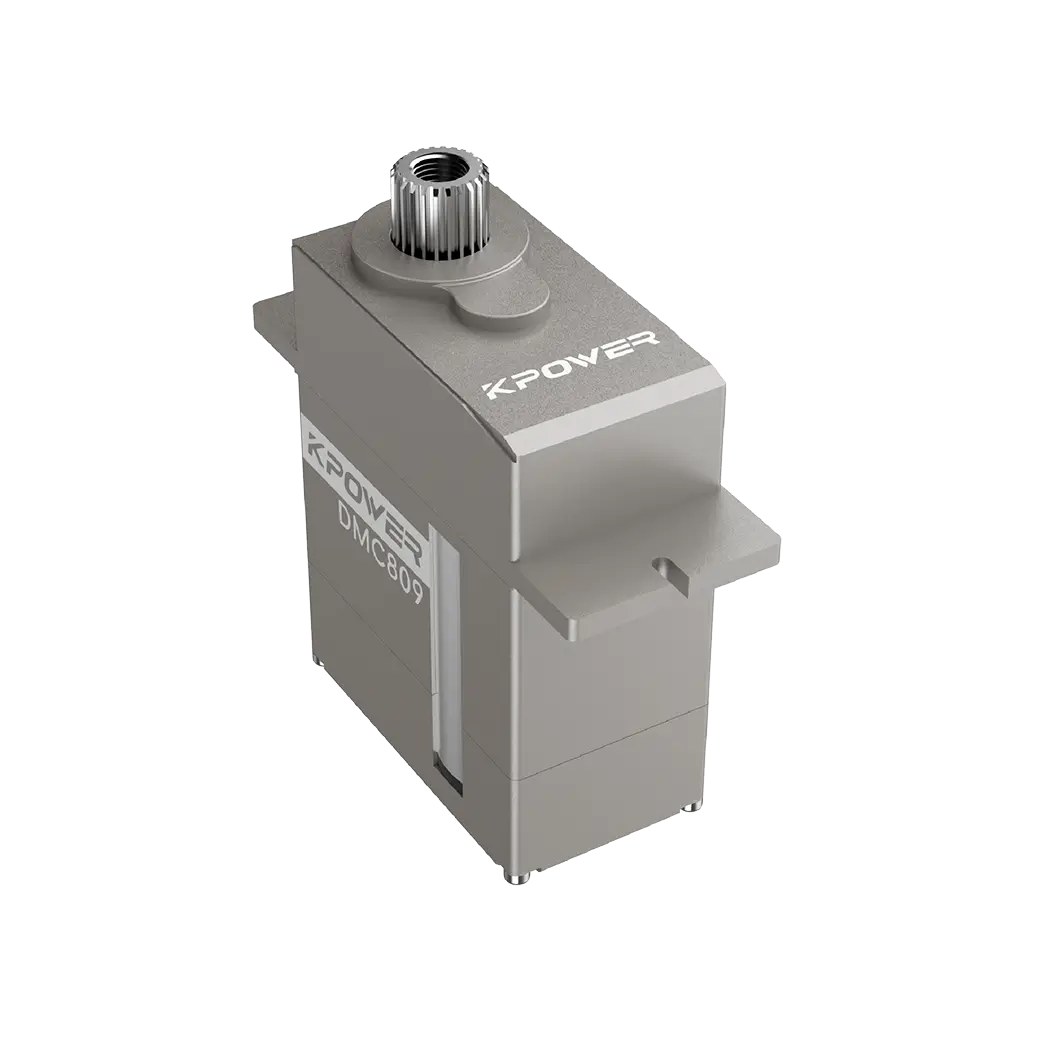
As a reminder, if you usekpowerServo, a high-precision servo, has a very fast response speed and is more sensitive to leading edge jitter. It is recommended that a 330Ω resistor be connected to the signal line to suppress ringing.
write()Control to microsecond levelThe Arduino environment provides the Servo library, but do you really understand it?
#includeServo myServo; void setup() { myServo.attach(9, 500, 2500); // Bind the pin and customize the pulse width range } void loop() { myServo.writeMicroseconds(1500); // Directly write microseconds → 90° delay(500); } There are omitted sentences. The default parameters of attach() are 544 to 2400µs. However, in fact, the servo is generally between 500 and 2500µs. If calibration is not performed, the angle will deviate.。
Calibrate the signal, extract it as the first keyword, and take out three actual measurement points, which are 0° equals 520µs, 90° equals 1480µs, and 180° equals 2460µs. Obtain the mapping table through linear interpolation, store the mapping table in the EEPROM, and read it every time it is powered on. This step must be done for professional-level projects.
What the reader has experienced is that when you enter write(90), the output is 87°. It is not that there is an error, but that you have not calibrated it. You have to execute a calibration function, and then the angle can accurately point to the position you set.
Control 12 servos? The number of PWM pins is limited. The PCA9685 module is recommended, which converts I2C to 16-channel PWM. It frees up Timer resources and its output frequency is independent.
Inductive reasoning: From single servo to multiple servos, common failure modes:

Insufficient current → Each servo is blocked according to the current1.5 times the total power supply calculated
Frame rate conflict → All servos must share the same cycle (20ms)
Update blocking → use non-blocking delay or timer interrupt
Speed change rhythm: at low speed, the pulse width is gradually changing and smooth; at high speed, the load needs to be predicted. Dynamic response, the second keyword, refers to the real-time ability of the servo to follow instructions. The optimization method is to use writeMicroseconds() to write the value directly to avoid the overhead caused by converting the angle into pulse width in the library.
Q: After powering on, the servo rotates violently to the bottom and vibrates?
The signal line is in a floating state, or the pin is not configured for output. The default high level is mistakenly read as the limit pulse width. Check the connection configuration immediately.。
Q: It gets stuck in the middle of rotation and is accompanied by a "sizzling" sound?
For case A, there is a voltage drop or drive overload. If the measured working voltage is lower than 4.5V, then the power supply needs to be replaced. Also remove mechanical stuck points.
Q: With the same code, some servos are normal and some are reversed?
A: The polarity of the mapping of pulse width and angle of different brands is opposite. The pulse width value corresponding to 0° and the pulse width value corresponding to 180° are exchanged to rewrite the mapping.
Q: How can I stay still for a long time without getting hot?
Wrong, it is wrong to stop sending PWM. It must be sent continuously to maintain the pulse width. Reducing the refresh frequency to 20Hz can have a cooling effect.
Q: The servo jumps randomly when Arduino is reset?
A: During the reset period, the pin will transition to a high-impedance state.Add a 10k pull-down resistor to ground, or use a dedicated PWM keeper instead。
Looking at the core, the accuracy of PWM comes down to the product of the influence of power quality, the results of pulse width calibration, and the stable state of timing, and the three phases. If any one of these is missing, it can be regarded as completely unsatisfactory.
Historically, analog servos rely on potentiometers for feedback, and digital servos rely on MCUs for analysis. However, the bottom layer is still PWM.. The trend in the future points to serial bus servos, such as half-duplex UART, but PWM is still the gold standard in education and small projects due to its simplicity.
Your next steps:
Really measure the waveform with an oscilloscope or logic analyzer (even a cheap module is better than blind guessing)
Create independent calibration curves for each servo
Leave a current margin (at least 50%) in the project
Reversal of perception: The steering gear is not a black box, but a practitioner of the art of time. Every pulse you send out is all carving an angle.
At this moment, pick up the Arduino, connect the servo, and start your first microsecond write operation. That precise rotation will give you feedback corresponding to all your efforts.
Angle is information, pulse width is power. Take control of it. *
Update Time:2026-05-06
Contact Kpower's product specialist to recommend suitable motor or gearbox for your product.


