

TECHNICAL SUPPORT


Published 2026-07-16
01How to Use aservoon Micro:bit: A Simple Wiring & Code Guide
Connecting aservomotorto a BBC Micro:bit is one of the most rewarding projects for beginners in robotics and embedded systems. It bridges the gap between simple LED blinking and complex mechanical motion. However, many users face issues like jittery movement, weak response, or even damaged boards due to power misunderstandings. This guide provides a clear, step-by-step approach to wiring, coding, and troubleshooting, ensuring your project runs smoothly from day one.
The Core Challenge: Power and Signal
The primary hurdle when using aservoon micro bitis not the code, but the power delivery. The Micro:bit's USB port provides 5V, but it can only supply limited current (usually around 500mA total for all pins). Standard servos, especially larger ones, require significant peak current during startup and movement. Drawing this directly from the Micro:bit's 3.3V regulator or USB line can cause voltage drops, leading to erratic behavior or resetting the board.
Therefore, the first rule is separation. You must separate the power source for the servo from the logic power of the Micro:bit. While they share a common ground, their energy sources must remain distinct to ensure stability. This isolation prevents noise from the motor from interfering with the sensitive microcontroller signals.
Essential Components and Wiring
Before writing any code, ensure you have the correct hardware setup.
BBC Micro:bit v2: Recommended for better pin availability and 3.3V logic level compatibility.
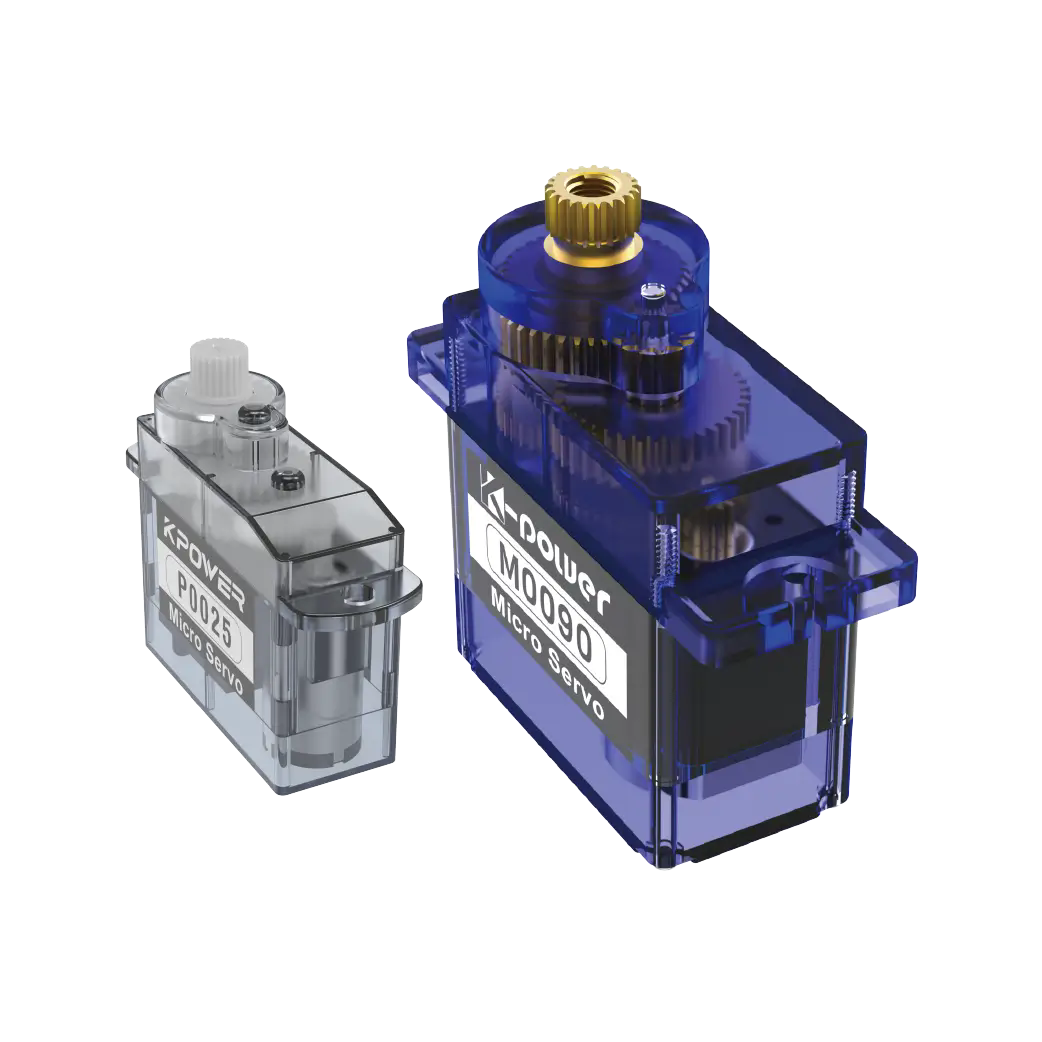
Servo Motor: Standard 9g micro servo or a larger metal-gear servo depending on torque needs.

External Power Supply: A 5V battery pack or wall adapter capable of providing at least 1A per servo.
Jumper Wires: Male-to-female for connections.
Wiring Diagram
1. Servo Red Wire (VCC): Connect to the positive terminal of the external 5V power supply.Do notconnect this to the Micro:bit's 3V or 5V pins.
2. Servo Brown/Black Wire (GND): Connect to the negative terminal of the external power supply. Crucially, also connect this wire to one of the GND pins on the Micro:bit (Pin 1, 2, or 3). This creates the "common ground" necessary for signal communication.
3. Servo Orange/Yellow Wire (Signal): Connect to Pin 0, Pin 1, or Pin 2 on the Micro:bit. Pin 0 is recommended for PWM (Pulse Width Modulation) support in most libraries.
By establishing this common ground, you allow the Micro:bit to send low-voltage logic signals to the servo without sharing the high-current load. This standard practice applies to almost allmotion control applicationsinvolving microcontrollers.
Coding the Servo Movement
Micro:bit makes servo control accessible through its block-based MakeCode editor or Python. The underlying principle is Pulse Width Modulation (PWM). The servo interprets the width of the electrical pulse to determine position.
Using MakeCode Blocks

1. Go to the "Advanced" section in the left-hand menu.
2. Find the "Servo" extension and add it.
3. Drag out theset servo 0 to angleblock.
4. Set the pin to Pin 0 and the angle to a value between 0and180 .
5. To create smooth motion, use a loop with small delays. For example, loop from 0 to 180 degrees, incrementing by 1 degree each time with a 20ms delay.
Using Python
If you prefer text-based coding, the microbit library allows direct PWM control, though using a servo-specific library is cleaner.
from microbit import
import servo
# Create a servo object on Pin0
my_servo = servo.Servo(pin0)
# Rotate to 90 degrees
my_servo.write_angle(90)
sleep(1000)
# Rotate to 0 degrees
my_servo.write_angle(0)
When implementing servo motor selection logic in code, remember that not all servos rotate exactly 360 degrees. Most standard servos are limited to 180 degrees. If you need continuous rotation, you must select a specific continuous rotation servo , which changes the coding logic from position control to speed control.
Troubleshooting Common Issues
Even with correct wiring, problems may arise. Here is how to diagnose them:
Jittering Noise : This usually indicates insufficient power or a poor ground connection. Ensure your external battery has enough capacity and that the GND wire is firmly connected to both the power supply and the Micro:bit.
Servo Won't Move : Check if the signal pin is connected to Pin 0, 1, or 2. Avoid Pin 3, 13, 14, etc., as they may not support the required PWM frequency. Also, verify that the servo is receiving 5V, not 3.3V, as some servos require the higher voltage to generate enough torque.
Micro:bit Resets : This is a sign of power starvation. The servo is drawing too much current from the Micro:bit's shared rail. Re-check your wiring to ensure the servo's VCC is connected only* to the external power source.
Best Practices for Reliability
To ensure long-term success, always test your servo under no-load conditions first. Then, gradually add mechanical load while monitoring temperature. If the servo becomes hot to the touch, it is likely stalled or overworked. Additionally, use a capacitor (eg, 100uF) across the servo's power terminals if possible. This helps filter out electrical noise generated by the motor brushes, protecting the Micro:bit's sensitive electronics.
Conclusion
Mastering how to use a servo on micro bit is a foundational skill in maker culture. By respecting power limits, establishing a solid common ground, and using appropriate PWM signals, you can achieve precise and reliable movement. Start simple, troubleshoot methodically, and expand your projects with confidence. Whether you are building a robotic arm or an automated gate, these principles apply universally to all servo control systems .
Update Time:2026-07-16

Contact Kpower's product specialist to recommend suitable motor or gearbox for your product.


