

TECHNICAL SUPPORT


Published 2026-07-12
Quick Answer
APWMservodriver boardtranslates control signals into precise motor movement, but not all boards deliver the same accuracy, heat management, or multi-axis synchronization. Choosing the wrong board often leads to jitter, overheating, or failed motion sequences — especially in multi-servoapplications like robotics, CNC, or industrial automation. The right board should match your voltage range, signal resolution, update rate, and thermal design. Before purchasing, verify the board's PWM frequency, current rating per channel, and protection features to avoid field failures that increase total cost of ownership.
01Introduction
Every year, production teams lose thousands of dollars not because theirservos are faulty, but because thePWM servo driver boardthey chose cannot handle the real-world load. Jittery arm movements on a pick-and-place line. Overheating during extended runtime. Servos that lose position mid-cycle. These symptoms rarely point to the motor itself — they point to the driver board.
When you are managing a multi-axis system, the board becomes the central nervous system. If it cannot deliver clean, consistent PWM signals under full load, your entire motion sequence degrades. Worse, repeated thermal stress shortens component life, forcing premature replacements that eat into maintenance budgets. The problem is not a lack of options. The problem is separating boards built for hobby prototyping from boards engineered for continuous industrial duty.
02Table of Contents
1. What a PWM Servo Driver Board Actually Does
2. Key Specifications That Determine Real-World Performance
3. How Board Design Affects Heat, Jitter, and Signal Loss
4. Multi-Axis Coordination: Why Channel Count Is Not Enough
5. Common Mistakes When Selecting a Driver Board
6. Specifications Comparison Table
7. Questions Buyers Often Ask About PWM Servo Driver Boards
8. Choosing the Right Board for Your Application
03What a PWM Servo Driver Board Actually Does
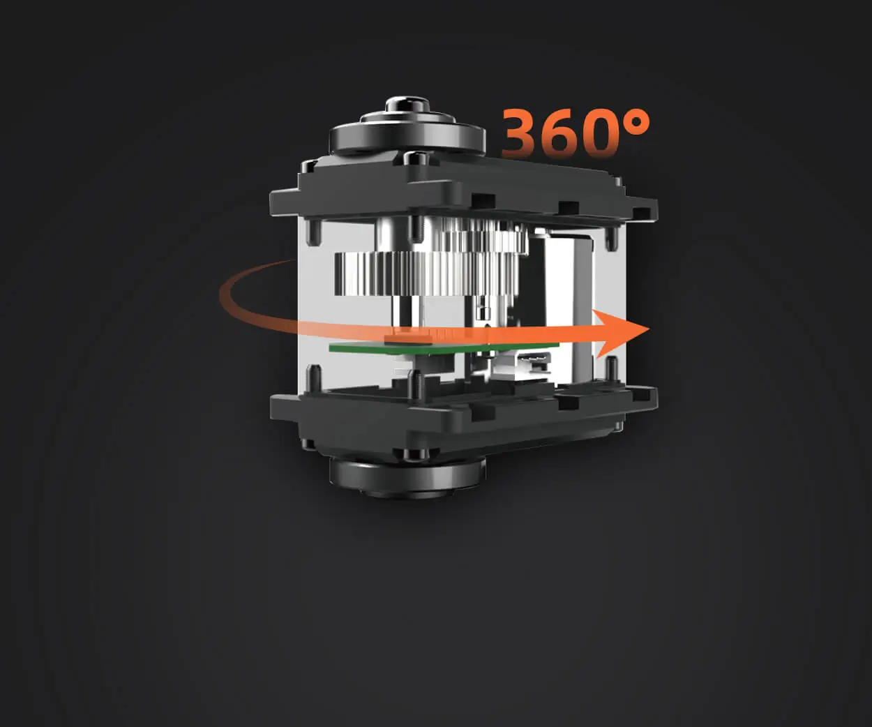
A PWM servo driver board receives a pulse-width modulated signal — typically between 1 ms and 2 ms at 50 Hz — and converts that into a corresponding angular position on the servo. For a single servo, almost any basic board works. But in production environments, the board must manage multiple servos simultaneously, maintain consistent timing across channels, and protect against spike voltages or current surges.
The core function is signal distribution and power regulation. Without proper signal conditioning, even a high-end servo will behave unpredictably. The board acts as the intermediary between your controller and each motor, ensuring that every channel receives the correct pulse width without cross-channel interference.
04Key Specifications That Determine Real-World Performance
Not all PWM servo driver boards are built to the same standard. When evaluating options, focus on these parameters:
PWM Frequency and Resolution
Standard servos operate at 50 Hz, but digital servos often perform better at higher frequencies, such as 200 Hz or 333 Hz. Boards that only support 50 Hz may introduce latency or reduced resolution with digital servos. Higher resolution — measured in bits or microseconds — allows finer position control.
Current Rating Per Channel
Continuous current draw by servo size and load. A micro servo may draw 500 mA, while an industrial servo can draw 3 A or more under load. The board must vary handle peak current without voltage drop. If the board undersupplies current, servos stall, overheat, or lose position.
Voltage Range and Regulation
Boards with a wide input voltage range — for example, 5 V to 8.4 V — offer flexibility across different servo types. Onboard voltage regulation protects servos from overvoltage conditions, which is critical when using batteries or unregulated power supplies.
Signal Isolation
In electrically noisy environments — near motors, inverters, or welding equipment — signal isolation prevents false triggers. Boards with optocouplers or dedicated isolation ICs are more reliable in industrial settings.
05 How Board Design Affects Heat, Jitter, and Signal Loss
Heat is the most common cause of premature driver board failure. When multiple servos draw current through a single board, the onboard voltage regulators and MOSFETs generate heat. If the board lacks a heat sink or proper copper pour design, temperatures rise quickly. Above 85°C, electrolytic capacitors degrade, solder joints weaken, and PWM signals become unstable.
Jitter — unwanted variation in pulse width — often results from poor clock source accuracy or insufficient decoupling capacitors. A board with a dedicated crystal oscillator and bypass capacitors on each channel produces cleaner signals. For applications requiring synchronized movement, such as robotic arms or camera gimbals, jitter tolerance is measured in microseconds.
Signal loss over long cable runs is another hidden issue. If your servos are located more than one meter from the board, voltage drop and signal attenuation become measurable. Boards with differential signal output or built-in cable compensation reduce this risk.
06 Multi-Axis Coordination: Why Channel Count Is Not Enough
Many buyers assume that more channels equal better capability. In reality, channel count matters only if the board can update all channels simultaneously at the required frame rate. Boards that use sequential update — updating one channel per cycle — introduce timing delays between servos. For applications requiring synchronized motion, such as walking robots or conveyor sorting systems, simultaneous update is essential.
Check whether the board uses a dedicated PWM controller IC (such as the PCA9685) or relies on software timing. Software-based boards are cheaper but introduce timing drift as the CPU load increases. Hardware-based boards maintain consistent timing regardless of how many servos are active.

07 Common Mistakes When Selecting a Driver Board
Mistake 1: Ignoring Power Supply Compatibility
A board rated for 6 V input cannot drive servos requiring 7.4 V. Always match the board's input range to your servo operating voltage.
Mistake 2: Overlooking Protection Features
Boards without reverse polarity protection, overcurrent protection, or thermal shutdown are risky in production environments. A single wiring error can destroy the board and connected servos.
Mistake 3: Assuming All Servos Use the Same Signal Standard
Some servos require inverted signals, extended pulse ranges, or different center points. Boards with configurable signal parameters reduce integration time.
Mistake 4: Choosing Based Only on Price
Low-cost boards often lack thermal management, signal filtering, and reliable connectors. The savings are quickly lost when field failures cause downtime.
08 Specifications Comparison Table
09 Questions Buyers Often Ask About PWM Servo Driver Boards
1. Can I use a 16-channel board for 12 servos running continuously?
Yes, but only if the total current draw does not exceed the board's power handling capacity. Verify the combined current at full load and compare it to the board's rated output.
2. What happens if the board's voltage is too low for my servos?
Servos will operate slower, with reduced torque, and may fail to reach commanded positions. Prolonged undervoltage can damage the servo motor windings.
3. How do I know if my board causes jitter?
If servos buzz, oscillate, or fail to hold position without external load, the board may be introducing signal jitter. Test with an oscilloscope to measure pulse width variation.
4. Do I need signal isolation for a factory automation setup?
In most factory environments with motors, drives, and welding equipment, signal isolation is recommended. It prevents electromagnetic interference from corrupting the PWM signal.
5. Can I drive analog and digital servos on the same board?
Yes, but analog servos are more sensitive to high-frequency PWM. If using a mixed setup, start with 50 Hz and verify performance before increasing frequency.
6. What is the maximum cable length between board and servo?
For standard PWM signals, keep cable length under 1.5 meters. Beyond that, use twisted-pair shielded cable or a board with differential output.
7. How often should I replace a PWM servo driver board in continuous use?
With proper thermal management, a mid-range or industrial board typically lasts 3–5 years. Entry-level boards may need replacement every 6–12 months under continuous load.
8. What is the most common failure mode of driver boards?
Overheating due to inadequate current handling or poor ventilation. The second most common failure is connector wear from repeated plugging cycles.
10Choosing the Right Board for Your Application
If you are building a single-axis test rig, an entry-level board may suffice. For multi-axis production systems, invest in a board with adjustable frequency, per-channel protection, and thermal management. The cost difference is often less than the value of one hour of unplanned downtime.
Start by listing your servo specifications — voltage, peak current, required frequency — then match those to a board that provides headroom of at least 20% on current and voltage. If your application requires synchronized movement across three or more axes, prioritize boards with hardware-based simultaneous update. For environments with electrical noise, signal isolation is not optional.
When comparing suppliers, ask for documentation on PWM accuracy, thermal testing, and connector reliability. A board that passes these checks will reduce maintenance frequency and improve motion consistency over the long term.
11 Need Help Selecting the Right PWM Servo Driver Board?
Choosing a driver board should not be a guessing game. If you are evaluating options for an upcoming project, send your servo specifications and motion requirements to the kpowerservo engineering team. They can review your application parameters and recommend a board configuration that balances cost, performance, and reliability. A quick technical review upfront often prevents months of field troubleshooting.
Update Time:2026-07-12

Contact Kpower's product specialist to recommend suitable motor or gearbox for your product.


