

TECHNICAL SUPPORT


Published 2026-07-10
01Quick Answer
Amicroservo9g diagramtypically shows three core elements: wire color coding (brown for ground, red for power, orange or yellow for signal), pulse width modulation (PWM) timing for positioning (1 ms for 0°, 1.5 ms for 90°, 2 ms for 180°), and mechanical dimensions including mounting hole spacing (approximately 23 x 12 x 29 mm). Understanding this diagram is essential for correct wiring, avoiding reverse polarity damage, and integrating theservointo motion control applications. Without proper interpretation, voltage reversal can destroy the control board instantly.
02Introduction
A production line stops because a microservofails within hours of installation. The motor runs, but the arm refuses to hold position. The engineer double-checks the wiring, only to discover the signal wire was connected to a voltage source instead of a PWM pin. This scenario repeats more often than most buyers expect. The problem is rarely the servo itself. The problem is that theMicro Servo9g diagramwas never fully before understood integration. wasted time, damaged components, and delayed projects. For procurement managers and engineering leads selecting these servos in bulk, a misinterpreted diagram can mean hundreds of units failing under identical conditions. Understanding every annotation on that diagram directly affects yield rates, maintenance frequency, and long-term system reliability.
03Table of Contents
1. What aMicro Servo9g Diagram Actually Contains
2. Wire Color and Signal Mapping: How to Avoid Wiring Errors
3. Mechanical Dimensions: Mounting, Clearance, and Load Limits
4. PWM Timing and Position Mapping: What the Diagram Does Not Show
5. Common Diagram Misinterpretations That Cause Failures
6. Key Specifications to Check Before Purchasing
7. Questions Buyers Often Ask AboutMicro Servo9g Diagrams
8. Choosing the Right Micro Servo for Your Application
04What a Micro Servo 9g Diagram Actually Contains
A standardmicro servo 9g diagramis a composite of three distinct sections: the wiring schematic, the mechanical outline with critical dimensions, and the electrical timing chart. The wiring section identifies each conductor by color and its corresponding function. The mechanical section provides overall length, width, height, mounting hole locations, and output shaft dimensions. The electrical section defines pulse width ranges for angular positions and operating voltage limits.

Many buyers assume the diagram is a simple reference. In reality, it is a compliance and compatibility document. Without verifying that the mounting hole spacing bracket matches your layout, or that the pulse width range aligns with your controller's output, the servo will not function as intended. The diagram is the first point of verification before any purchasing decision.
05Wire Color and Signal Mapping: How to Avoid Wiring Errors
The most common failure in micro servo 9g integration is reversed polarity. The diagram always specifies the ground wire as brown or black, the power wire as red, and the signal wire as orange, yellow, or white. Yet engineers frequently connect the signal wire to a 5V supply pin instead of a PWM-capable GPIO. This mistake burns out the internal control circuit within seconds.
A properly interpreted diagram tells you not only which wire is which, but also the voltage tolerance range. Most 9g micro servos operate between 4.8V and 6.0V. Exceeding 6.0V, even briefly, can damage the motor driver IC. When reviewing a diagram, confirm that your controller's logic level matches the servo's signal voltage requirement. A 3.3V controller may not trigger a 5V servo reliably,leading to intermittent positioning errors. For buyers evaluatingcustom servo solutions, verifying signal compatibility at the diagram stage prevents costly redesigns.
06Mechanical Dimensions: Mounting, Clearance, and Load Limits
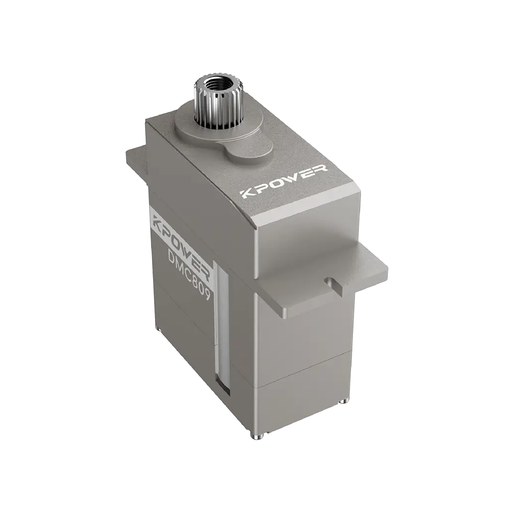
The mechanical section of amicro servo 9g diagram includes dimensions that directly affect installation success. Typical measurements are approximately 23 mm in width, 12 mm in height, and 29 mm in depth. Mounting hole spacing is usually 26 mm center-to-center for M2 screws. The output shaft diameter is commonly 4.8 mm with a 24-tooth spline.
What the diagram rarely shows is the clearance required for the servo horn rotation. If your enclosure restricts the horn's arc, the servo will stall, overheat, and fail. Additionally, the diagram does not specify the maximum load for the output shaft bearings. Exceeding the radial or axial load limit causes premature gear wear. When selecting servos for continuous or high-torque applications, request a torque curve or load specification separately. The diagram alone is insufficient for mechanical design validation.
07 PWM Timing and Position Mapping: What the Diagram Does Not Show
The electrical timing section of the diagram typically lists three pulse widths: 1 ms for 0°, 1.5 ms for 90°, and 2 ms for 180°. This standard assumes a neutral position at 1.5 ms. However, not all servos follow this exact mapping. Some manufacturers use 0.6 ms to 2.4 ms ranges for extended rotation. Others have a narrower deadband, meaning the servo responds to smaller pulse width changes.
A critical detail missing from most diagrams is the pulse refresh rate requirement. Most micro servos expect a 50 Hz signal, or 20 ms period. Sending a higher frequency signal, such as 100 Hz, can cause jittering, overheating, or loss of position hold. When integrating into a motion control system, verify that your controller's PWM frequency matches the servo's specification. refresh If the diagram does not list rate, contact the supplier. Without this parameter, the servo behavior is unpredictable.
08 Common Diagram Misinterpretations That Cause Failures
Three diagram errors occur frequently in procurement and engineering teams. First, assuming all servos with the same physical size have wiring. Some manufacturers swap signal and power wire colors. Always verify against the specific diagram for your model. Second, ignoring the operating voltage range. A diagram may list 4.8V to 6.0V, but some buyers power the servo from a 5V regulator without checking current draw. erratic movement and reset loops.
Third, misreading the mechanical zero position. The diagram shows the output shaft at 0° with the horn oriented perpendicular to the servo body or parallel depending on the manufacturer. Installing the horn without confirming this reference results in a 90° offset, making position control impossible. For buyers managing servo motor selection across multiple projects, standardizing on one diagram interpretation method reduces cross-model errors.
09 Key Specifications to Check Before Purchasing

Thisservo motor selection checklist should be cross-referenced with your controller specification and mechanical enclosure before ordering. A mismatch in any one parameter negates the servo's usability in your application.
10 Questions Buyers Often Ask About Micro Servo 9g Diagrams
Q1: Is the wire color standard for all 9g micro servos?
Not always. Most use brown for ground, red for power, and orange for signal, but some manufacturers swap signal and power. Always verify against the specific diagram provided with your order.
Q2: Can I use a 3.3V controller with a 5V micro servo?
Possibly, but signal voltage may be too low to trigger the servo reliably. Use a level shifter or select a servo rated for 3.3V logic. The diagram should list signal voltage requirements.
Q3: What happens if I reverse the power and ground wires?
The servo's control board will be damaged almost instantly. Reversed polarity sends current through the protection diode or directly into the IC, causing permanent failure.
Q4: Does the diagram show the maximum torque rating?
Typically no. Torque is listed separately in the datasheet. The diagram only shows mechanical dimensions and wiring. Request the full specification sheet for torque and speed data.
Q5: Can I run a 9g micro servo at 7.4V?
No. Most 9g servos are rated for a maximum of 6.0V. Exceeding this voltage leads to overheating, motor damage, or complete failure. Check the diagram or datasheet for exact limits.
Q6: Why does my servo jitter even though the wiring is correct?
Possible causes include incorrect PWM frequency, insufficient power supply current, or electrical noise on the signal line. Verify the controller outputs a 50 Hz signal and that the power source can deliver at least 1A.
Q7: What does the 9g in the name refer to?
The weight of the servo, approximately 9 grams. This is an approximate value and can vary by 1–2 grams depending on cable length and horn material.
Q8: Can I extend the servo cable beyond the length shown in the diagram?
Yes, but longer cables increase resistance and susceptibility to noise. For runs over 30 cm, use twisted-pair signal wire and a capacitor near the servo to filter voltage ripple.
Q9: How do I confirm the mechanical zero position from the diagram?
The diagram usually indicates the output shaft orientation at 0° pulse width. Some show the shaft centered with splines aligned horizontally. If unclear, request a dimensional drawing with zero position annotation.
Q10: Is the PWM timing the same for analog and digital servos?
The pulse timing range is similar, but digital servos accept higher update rates and offer faster response. Analog servos typically require a 50 Hz signal, while digital servos can handle up to 200 Hz. Check the diagram or datasheet for your specific model.
11Choosing the Right Micro Servo for Your Application
Interpreting a micro servo 9g diagram correctly is the first step toward avoiding integration failures, but it is not the final step. The diagram tells you what the servo is. It does not tell you whether the servo is right for your application. For continuous rotation applications, a standard positional servo will not work. For high-vibration environments, plastic gears wear out quickly, and a metal version gear becomes necessary. For projects requiring precise repeatability, a servo with a narrower deadband and digital feedback is a better choice.
Before placing an order, compare the diagram specifications against your controller output, mechanical constraints, and operational environment. Verify torque requirements by calculating load inertia and acceleration. Confirm that the power supply delivers sufficient current without voltage drop. If your application demands extended cable runs, include filtering components in your design.
For buyers managing procurement across multiple projects, consider standardizing on one servo model and diagram format. This reduces wiring errors, simplifies inventory management, and allows engineering teams to develop reusable control libraries. If you are evaluating custom servo solutions for unique requirements, ensure the supplier provides a detailed diagram with all dimensions, timing parameters, and environmental ratings.
Need help selecting the right micro servo for your application? Contact our engineering team with your mechanical drawings and control specifications. We can review your diagram requirements and recommend a solution that matches your performance targets and budget constraints.
Update Time:2026-07-10

Contact Kpower's product specialist to recommend suitable motor or gearbox for your product.


