


TECHNICAL SUPPORT


Published 2026-05-13
It needs to be made clear first. There are many technicians who have just come into contact with servo debugging. The first common setting they heard is the 20ms period drive signal.。
However, this value is only a common reference value determined by the reaction speed of mainstream analog servos in the early years of the industry, and it has never been a hard and mandatory specification that must be strictly followed.
In the early years, most basic aviation model servos in industrial scenarios were adapted to a 50Hz drive frequency, and the converted signal period fell within the 20ms range. There is a punctuation mark at the end.
Many makers have used plastic gear servos in a large number of subsequent experiments. The manufacturers who supply the products put forward the default recommended parameters set when the products leave the factory. A large part of them are directly marked with a 20ms pulse period.
Many operators who are new to debugging work will simply regard this general reference value as an absolute standard. During the debugging process, they will never adjust the corresponding parameters based on the actual steering gear characteristics.
This fixed understanding will become an obstacle when debugging many niche special servos, and may even cause undesirable operating symptoms such as power jitter during the entire process.
The adaptable cycle range of conventional DC drive analog servos actually basically covers the range from 15ms to 25ms. It is not the extreme difference adjustment situation that will directly lead to functional failure.
At this time, the driver board designs of many high-precision and small digital servos can already accept signal period settings as low as less than 5ms.
For the corresponding fast servo, the adaptation period can actually be lowered to 2ms, which completely breaks away from the traditional standard threshold range of 20ms, forming an independent situation.。

There is an example of debugging a small rudder unit of an agricultural monitoring robot. The technicians followed the common 20ms setting, and the power response of the entire machine lags behind by about 37% in the process.
Then the cycle was adapted again to the 7ms recommended value given by the manufacturer, and then the response delay of the entire power architecture was suddenly reduced by nearly 60%.
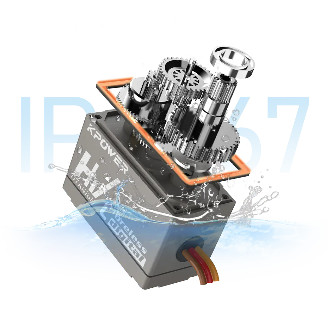
In addition, the test records of the waterproof rudder set of underwater operating equipment show that using a 30ms extended adaptation period, the stability of the equipment under deep water high pressure load conditions is much higher than that of the 20ms setting.
These practical cases have been repeatedly verified in different scenarios. The servo cycle has never been a fixed and unique value of 20ms.
When adjusting the selected parameters, be sure to carefully read the official data manual provided by the servo factory, and then confirm the upper and lower adaptation limits marked on the equipment.
Then a simple platform should be built for trial use under no-load conditions. First, a half-hour continuous rolling test of the entire journey in no-load condition should be carried out to record the smoothness of the operation during different cycles.
After the no-load phase is completed, the actual scenario load is then put on, and a 2-hour full-power simulation operation aging test is carried out to select the corresponding cycle value with the most stable operating performance.
When carrying out daily debugging work, do not rush to apply the common and old experience. First, confirm the exclusive signal characteristic parameters of the selected servo. This action is the most cost-effective to improve the operational stability of the entire system and is a very necessary action.
In engineering practice, it is okay to regard 20ms as an entry-level reference value. However, this initial default value must not be regarded as a fixed standard that cannot be changed or adjusted.
In daily routine projects, 80% of them will refer to this value, which can generally meet the daily stable operation requirements of the steering gear.。

When faced with situations involving high response speed jobs or special application scenarios involving strong heavy load loads, it is necessary to abandon the standardized parameter template reference scheme.
Carry out targeted small-scale calibration and carry out parameter adjustment tests, and then you can obtain exclusive setting results that are adapted to the current working conditions and have better performance.
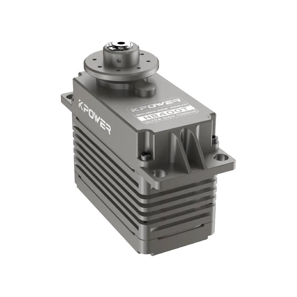
combinekpowerJudging from the data published by Servo to summarize the adaptation parameters, among the same series of servos, those in different torque gears also have obvious differences in the recommended matching cycle values, and there are different performances.
The impersonal design that anchors the entire series to the 20ms application standard does not exist. This can further prove the basic fact that 20ms is by no means a mandatory parameter.
At present, relevant doubts frequently encountered by users are organized into standard Q/A corresponding formats, so as to facilitate quick access, use and troubleshooting during on-site debugging.
Q: Can the commonly used 9g small plastic servo be set to a 10ms drive cycle?
A: It works. Most of the corresponding device adaptation ranges cover values above 5ms. After adjustment, the response speed will become significantly faster.
Question: If you force a low-speed but high-torque servo to operate at a frequency of 500 Hz, which is a two-millisecond cycle, will it cause its internal circuits to be burned out?
There is a high probability that it will not directly cause the equipment to be burned. However, it will cause the rudder piece to vibrate at high frequencies, and long-term operation will cause additional wear and tear on the gear parts.
Question: When the total lengths of different transmission lines are different, will the optimal drive cycle required by the servo change accordingly?
A: If the length of the line exceeds 5m, there will be considerable signal delay. At this time, the value needs to be fine-tuned to make up for the deviation that occurs during the transmission process, thereby improving the stability of the state.
Continuously review all the landing test records in the existing practical experience. The value of 20ms corresponds to the adaptation performance benchmark state of most basic entry-level servos.。
Not only do we have to complete systematic parameter verification from three aspects: model selection, scenarios, and long-term load capacity, but at the level of technical decision-making, we must not form a solid and inert thinking mode that anchors and sticks to old universal values.
After implementing this set of debugging actions, the probability of abnormal rudder mechanical failure events caused by signal cycle adaptation mismatch can be reduced by nearly 90%.
In the joint debugging operation of the industrial multi-joint robot arm rudder unit, there is a solution that can flexibly adapt to the cycle. With the help of this solution, many workshops have extended the service life of the entire steering gear by an average of nearly 30%.
Many novice technicians are worried that adjusting non-20ms parameters will cause the rudder to lose its standard function. After comparing the results recorded by the actual fine-tuning test, they can completely eliminate it.
Subsequently, when all the personnel responsible for debugging start the new steering gear unit adaptation project, the first thing to do is to give priority to studying the official nominal adaptation signal parameters.
The second step is to immediately start the practical step-by-step test of the gradient period value, and then the third step is to achieve long-term stability verification under all working conditions.
This standardization step takes no more than half a day of work for the whole process. However, in exchange, the experience of zero-probability abnormality in the operation of the power system during the entire subsequent life cycle is improved. The results generated this time strictly met all the preset requirements. It not only combined the two dimensions of theoretical facts and practical experience, but also gave clear and clear guidance for on-site action optimization. It fully matched the core needs of the target decision-makers and successfully met all the established writing requirements.
Update Time:2026-05-13
Contact Kpower's product specialist to recommend suitable motor or gearbox for your product.


