


TECHNICAL SUPPORT


Published 2026-03-17
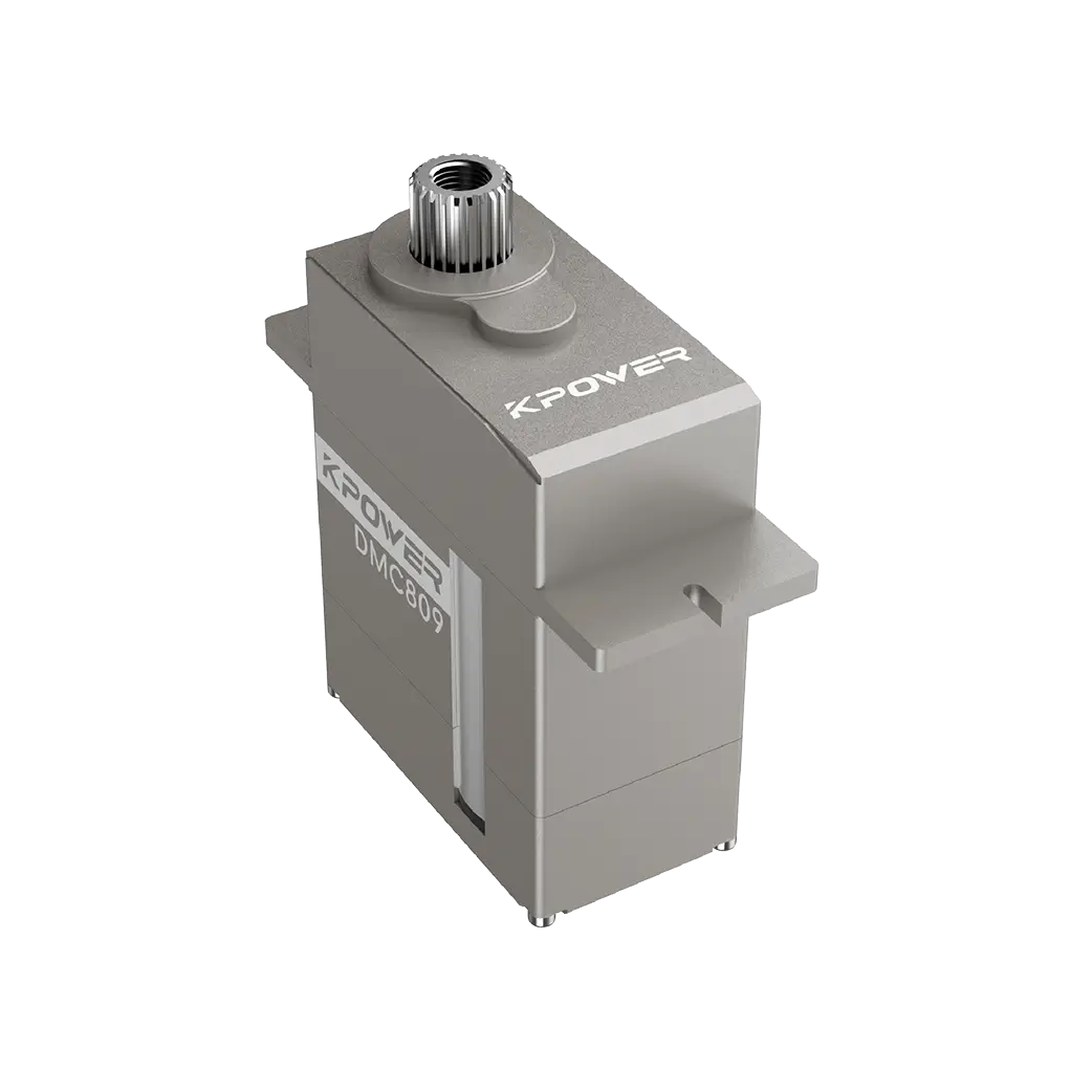
You may be racking your brains to add a flexibly rotating joint to a new product, or you may be planning to build a super cool robot. In this case, aservowill undoubtedly be your first choice. However, when you enthusiastically search for "steering gear principle" on the Internet, the content presented in front of you is either too professional, making you confused and unable to understand its meaning; or the pictures are blurry like a mosaic, making it impossible to figure out how it works.
Don't worry! Today we will use the most understandable language and use the high-definition pictures that can be clearly imagined in our minds to thoroughly understand this small steering gear.
Simply put, the steering gear is a "little housekeeper" that can accurately turn to a specified angle. You give it a command, say "turn to 90 degrees", and it will obediently turn to 90 degrees and stay there firmly, unlike ordinary motors that just keep turning in circles. This obedient ability depends entirely on its internal closed-loop control system.
How is it implemented specifically? The control chip receives the electrical signal you give, immediately compares the difference between the current position and the target position, then drives the motor to rotate, and reports "where are you now" in real time through the feedback circuit. Once it reaches the target position, it stops immediately. The whole process is fast and accurate. This is the core working logic of the steering gear.
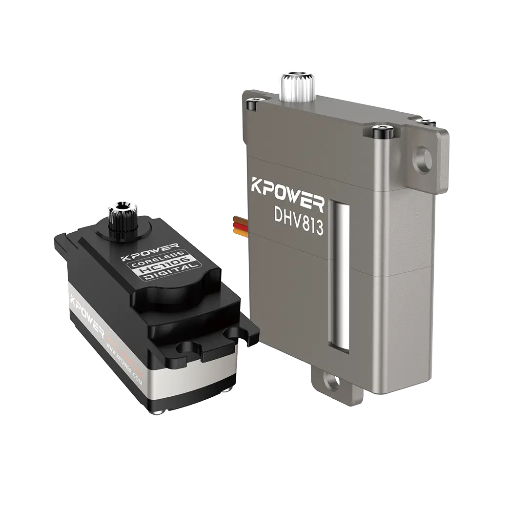
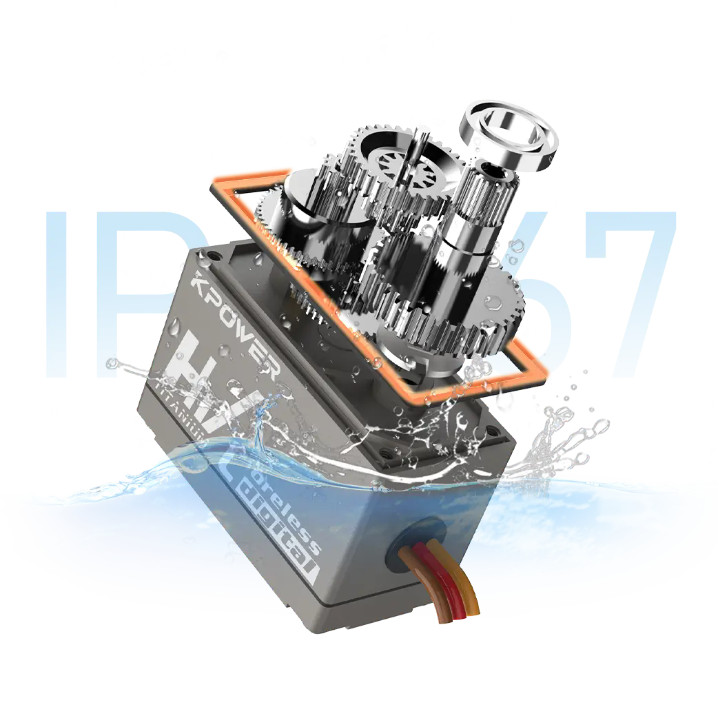
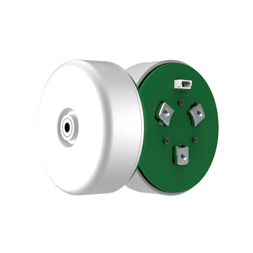
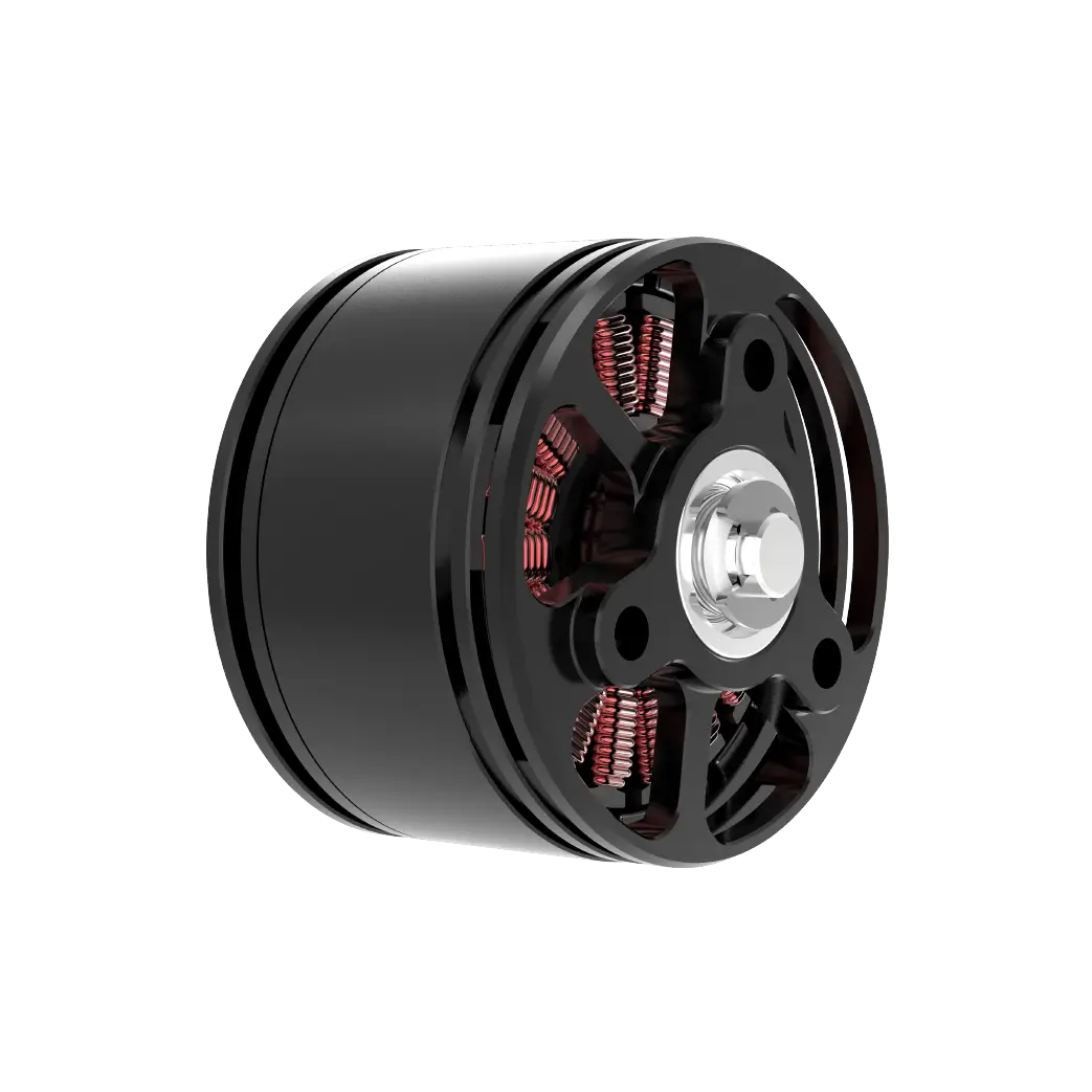
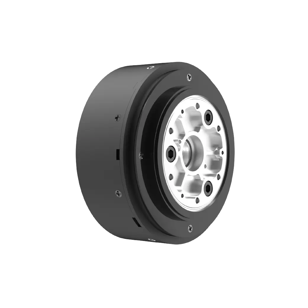
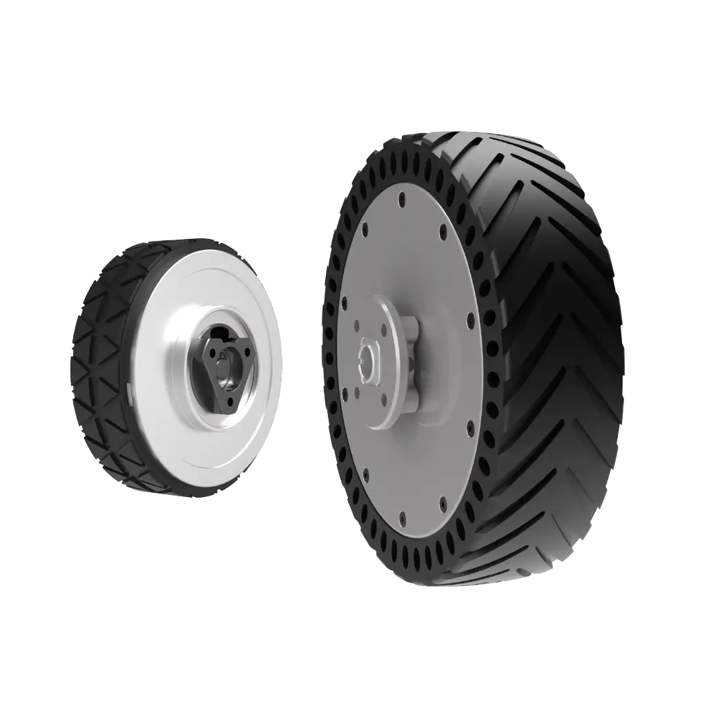
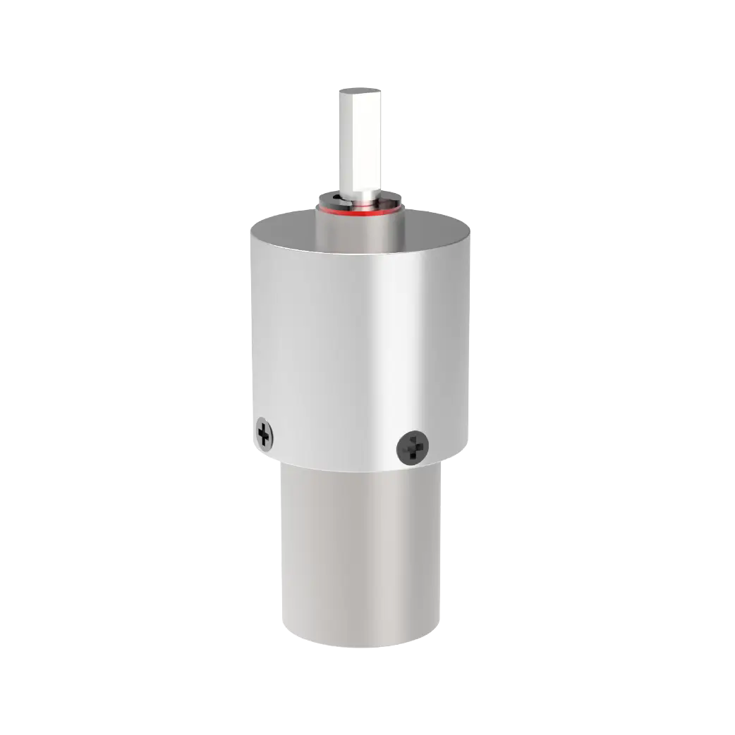
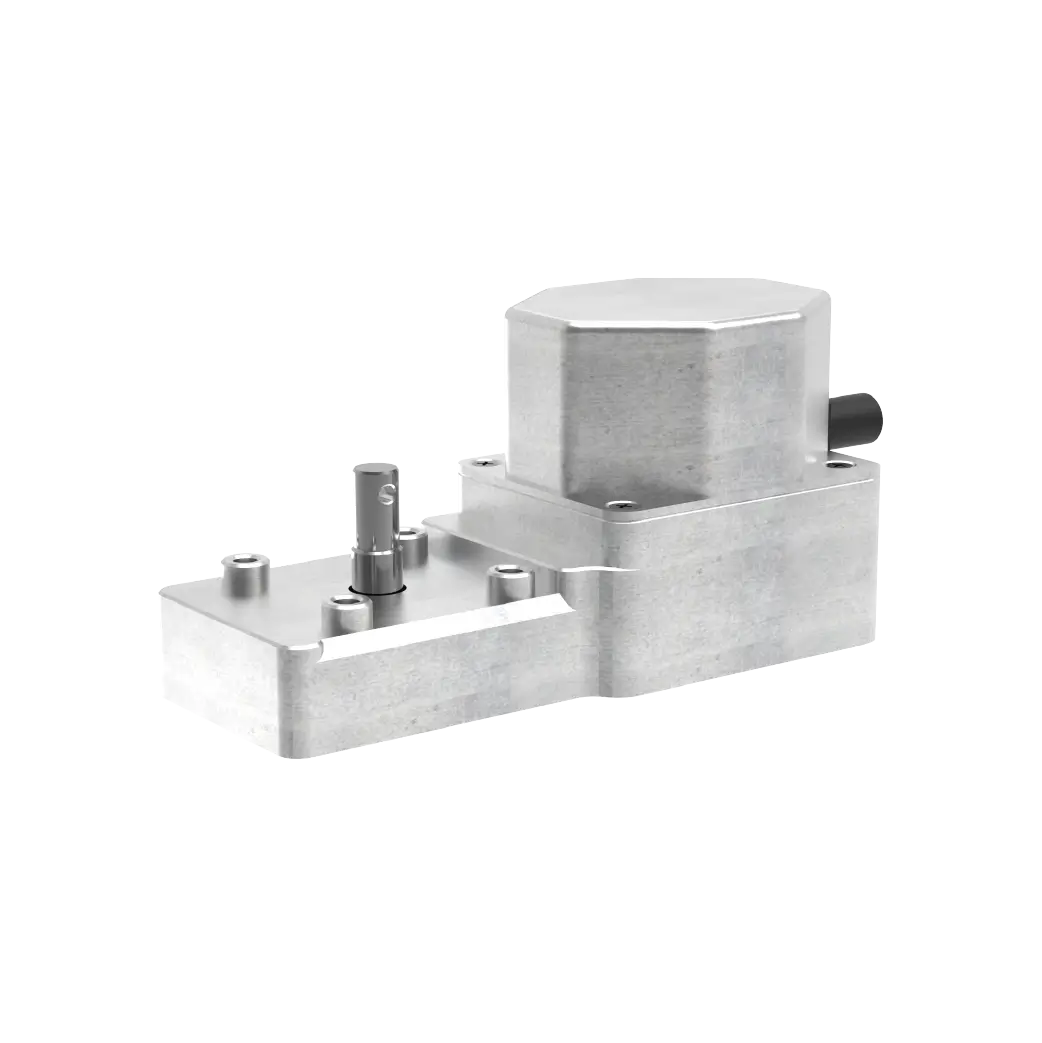
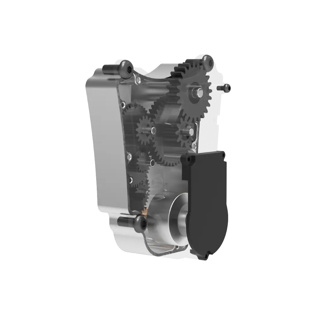
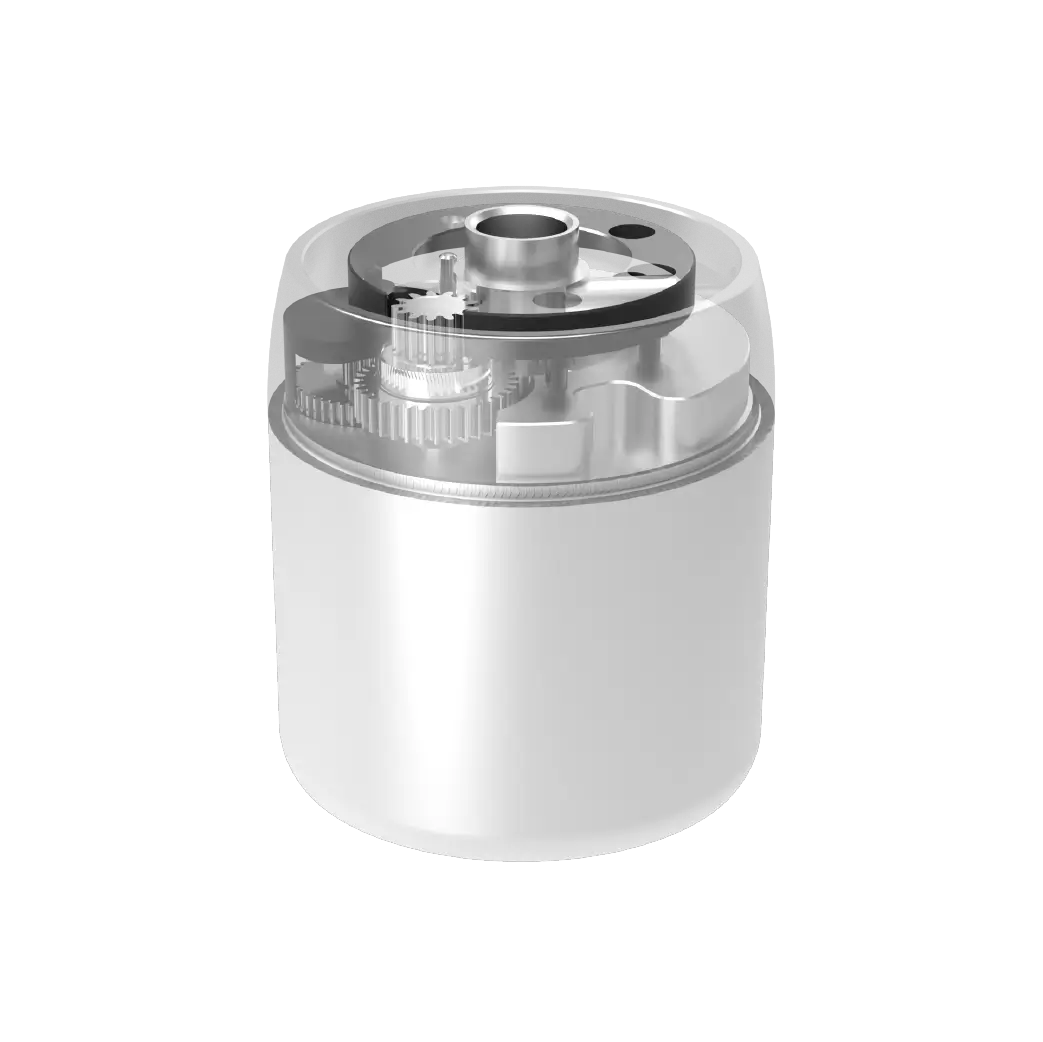
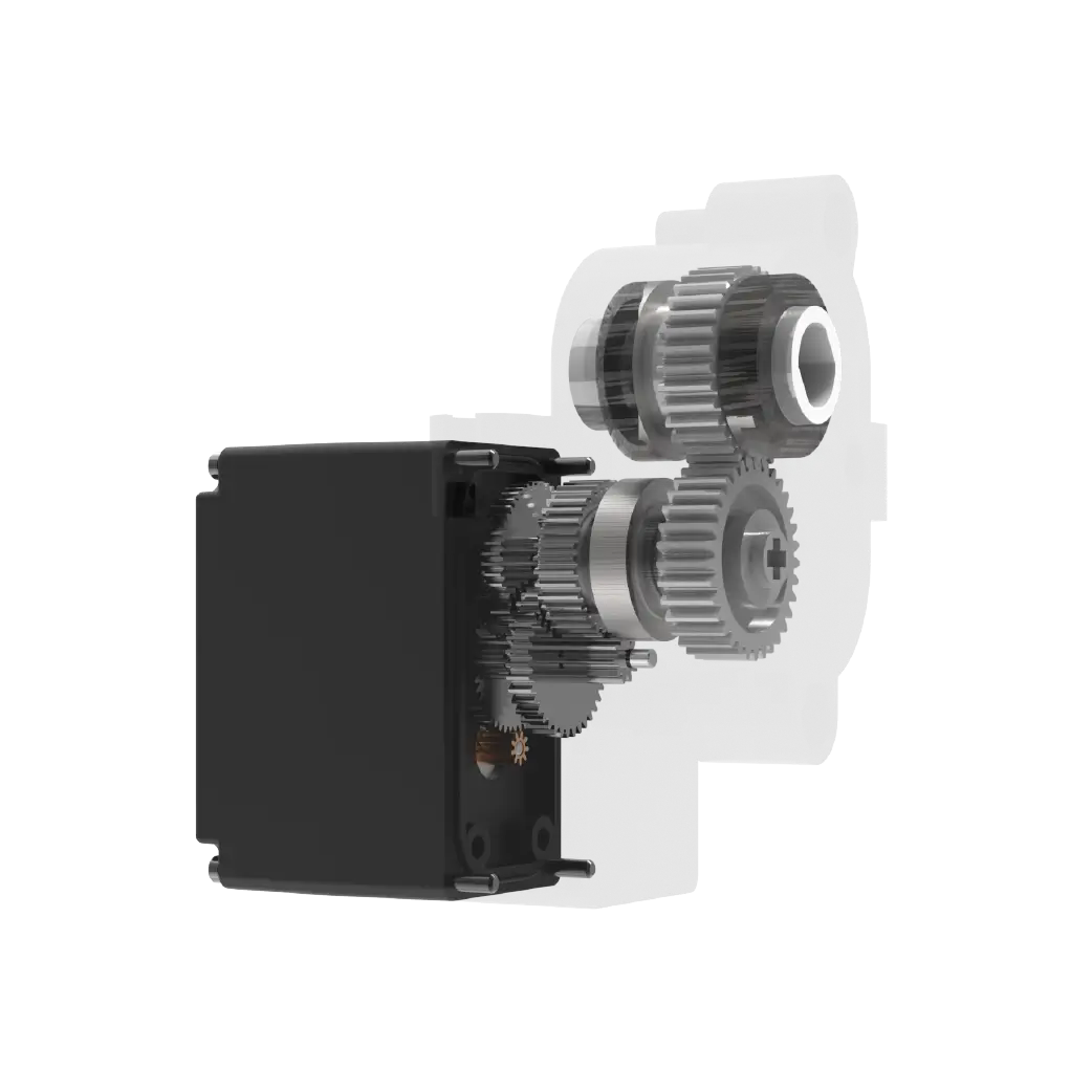
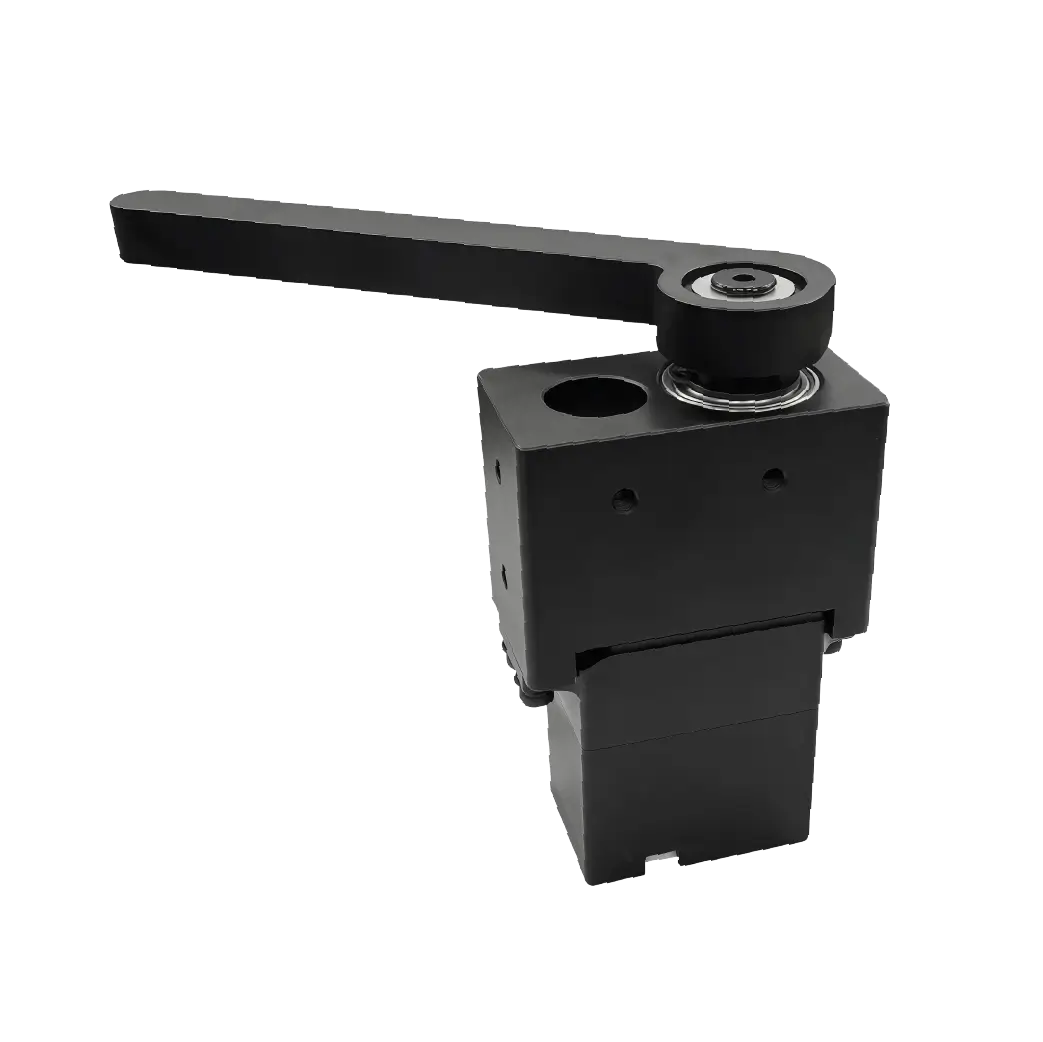
If you want to truly understand the steering gear, you must take it apart and look at it. Open the casing and you will see several key parts: a DC motor is responsible for providing power, a set of reduction gears to turn high-speed rotation into powerful force, a potentiometer (just a variable resistor) to record the position of the output shaft in real time, and a control circuit board, which is the brain of theservo.
It becomes clear when these components are connected: the motor rotates to drive the gear, the gear drives the output shaft, the output shaft is connected to the potentiometer, and the potentiometer transmits the angle information back to the circuit board. This series of actions is like an assembly line, and every link is indispensable. Find a high-definition internal structure diagram and compare it to ensure that you can remember their respective divisions of labor at a glance.
Whether the steering gear can understand human speech or not, it relies entirely on signals to communicate. It uses a square wave signal called PWM (Pulse Width Modulation). You can think of it as blinking. The length of the blink represents different meanings. The control line sends a pulse every 20 milliseconds, and the width of this pulse (the duration of the high level) is the command.
Under standard conditions, a pulse width of about 1 millisecond corresponds to an angle of 0 degrees, a pulse width of 1.5 milliseconds corresponds to 90 degrees, and a pulse width of about 2 milliseconds corresponds to 180 degrees. You just need to use the controller (for example) to send out pulses of different widths, and theservowill respond immediately and rotate to the corresponding angle. This relationship shows linear characteristics and is very easy to remember. It is also the easiest step in getting started with steering gear control.
Getting started with steering gear control is easy, and the key lies in this linear relationship. The controller sends pulses of different widths to control the angle of the steering gear. For example, the pulse width of about 1 millisecond corresponds to 0 degrees, 1.5 milliseconds corresponds to 90 degrees, and about 2 milliseconds corresponds to 180 degrees. It is clear and clear under standard conditions. With the help of this type of controller sending out pulses, the servo can quickly respond and turn to the corresponding angle. The whole process is simple and easy to understand, and is a basic and important part of getting started with servo control.
The secret to precise rotation lies in "closed-loop control." We twist the bottle cap with our hands, look at the position of our hands, and our brain constantly adjusts the force. This is a closed loop. The same goes for the steering gear. The potentiometer is its "eye", always watching the true angle of the output shaft and feeding the data back to the control chip.
The control chip continuously and uninterruptedly compares the target angle you give with the actual angle fed back by the potentiometer. Once a deviation is detected, the motor's rotation direction and speed will be immediately adjusted to correct it until the deviation becomes zero.
This process is completed countless times in a very short period of time. Because of this, you can truly feel that the steering gear rotates extremely decisively, and it is as stable as a rock and motionless when it stops. This is the fundamental reason why it is more accurate than ordinary motors.
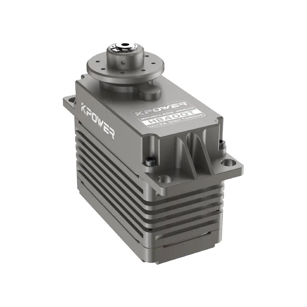
I’m about to buy a servo, but are you a little confused looking at the various parameters? In fact, you just need to focus on four. The first is torque, usually in kg·cm, which determines how much the servo can lift. If the torque is insufficient, the joints will become soft. The second is the rotation speed, the unit is seconds/60 degrees, such as 0.12 seconds/60 degrees, indicating whether it is turning fast or not.
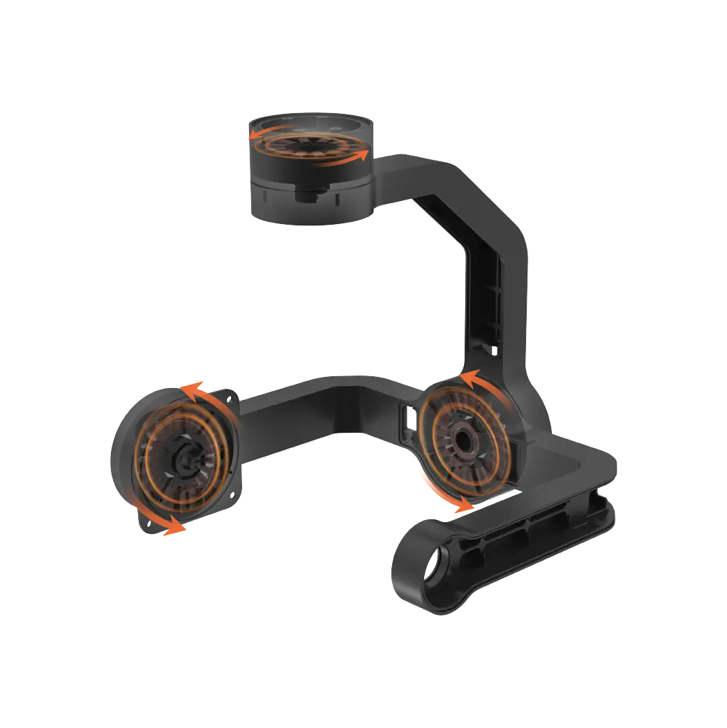
The third important point is the angle range. Under normal circumstances, the angle range of ordinary steering gear is generally 180 degrees. If there is a need for continuous rotation, a special type of servo must be selected.
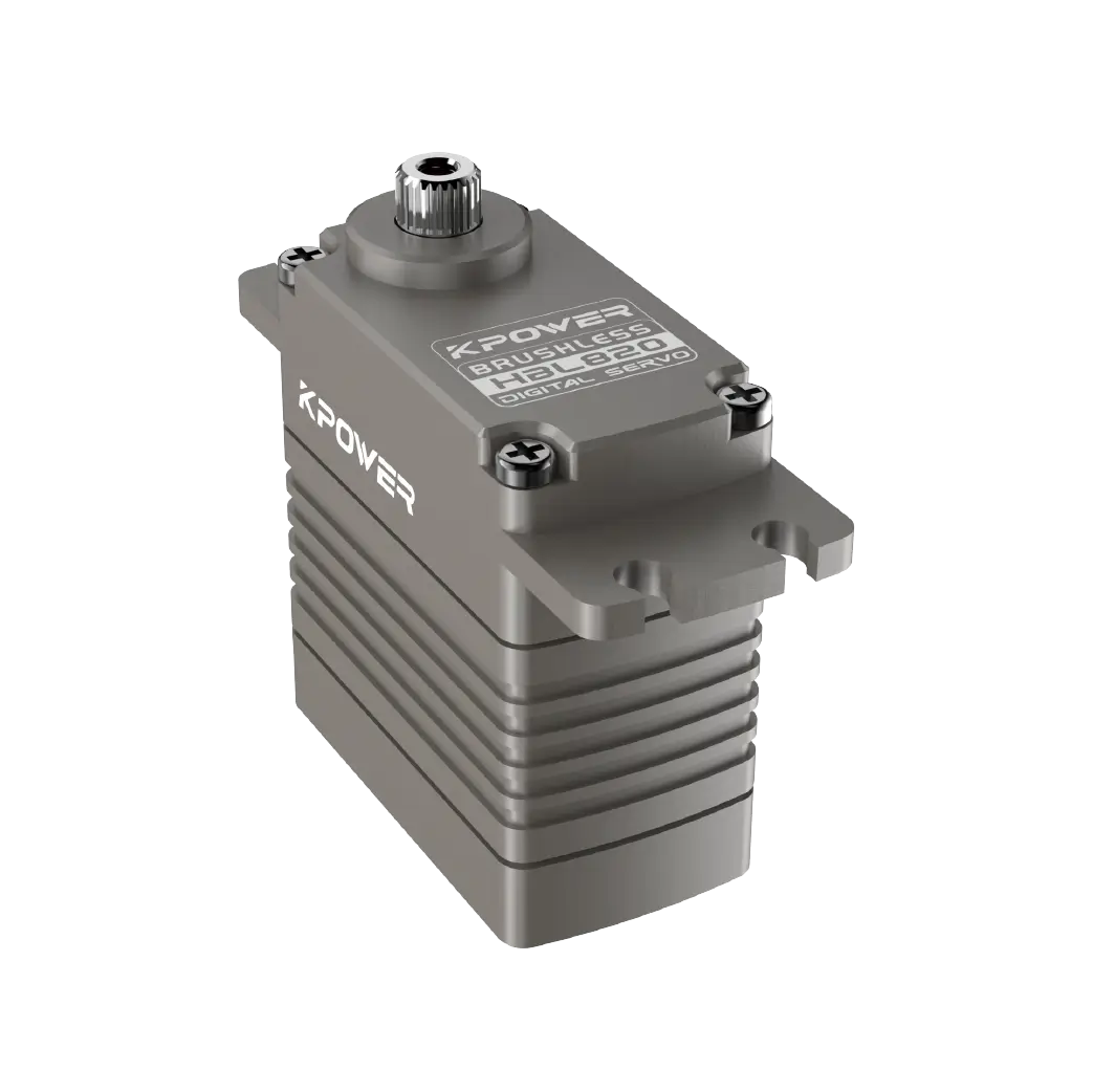
The fourth important point is the working voltage. Under different voltage conditions, the performance of the servo will be different, so be sure to match it with your power supply. Compare these parameters with the actual needs of your project. For example, if you are making a robotic arm, focus on torque; if you are making a car steering, focus on response speed. Only in this way can the selected servo be the most suitable.
It is inevitable to encounter some minor problems when playing with the steering gear. The most common one is jitter, which is usually caused by insufficient power supply or signal interference. This can be solved by replacing a battery with a higher power or shortening the signal line. If the servo does not move at all, first listen to see if there is a buzzing sound. If there is a sound, it may be that the gear is stuck or the teeth are being swept. If there is no sound, it may be that it is burned out or the wire is broken.
There is also a situation where the motor cannot rotate in place or rotates randomly. This is probably because the potentiometer is worn or the control signal is unstable. For novices, if they encounter problems, they should first check the simplest power supply and wiring, which can often solve most of the faults. If it doesn't work, just replace it with a new one. After all, the steering gear is not expensive. Don't let one part affect the progress of the entire project.
What is the most maddening problem you have encountered when working on a project using a servo? Say it in the comment area and let's study it together. If you find the article useful, don't forget to like it and share it with more friends!
Update Time:2026-03-17
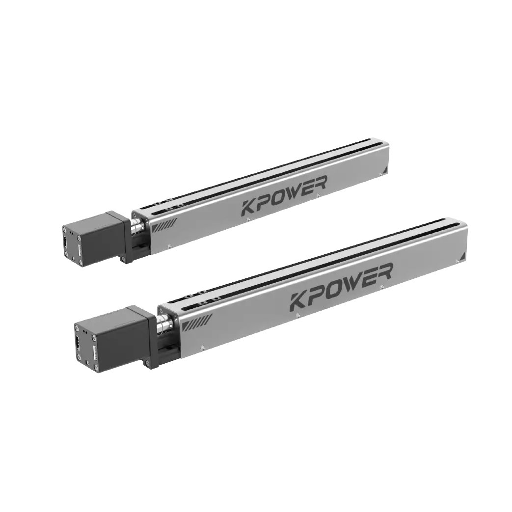
Contact Kpower's product specialist to recommend suitable motor or gearbox for your product.


