


TECHNICAL SUPPORT


Published 2026-05-21
In late spring, on an ordinary afternoon with sycamores fluttering by the window of the workshop, there were many players with soldering wires and new R&D personnel with digital modeling textbooks scratching their heads at the spread out bitmaps. This kind of scene is extremely common. The diagram that everyone talks about is a simple line diagram filled with signal paths and pin labels. It istheservocontrol schematic diagramthat allows the small swing arm to be accurately stuck to the set angle. Many people will regard it as a piece of waste paper full of meaningless lines when they first come into contact with it. It is only after burning three driver boards that they come to their senses. This picture is a "treasure map" of the entire rudder system.
01Easy level: the basic picture viewing logic of the bare board that is powered on by default
Most newcomers who have no experience in this industry will encounter the biggest pitfall when they step into the door. They study tenaciously on the densely packed resistor and capacitor parameters from the beginning, but ignore the extremely critical prerequisite of your power supply direction. Here is a data commonly known in the industry. 92% of the low-level mistakes made by novices are caused by incorrectly connecting the 5V signal line to the high-voltage pin of the power supply. Before the pulse width signal starts to be sent, theservomotor gets stuck and burns out, leaving no chance for remediation.
Under this basic situation, you only need to follow the guidance of the VCC connection in the picture and point out the position of the positive terminal one by one, then point out the location of the filter capacitor, and then point out the location of theservopower supply pin. In this way, you can sort it out, and there is no need to understand the details of the complex PID algorithm in advance.
Don't blindly look for tutorials that are more difficult than the standard and forcefully overcome them at this time. You should calmly take the blank schematic diagram you just bought and draw three times along the running trajectory of each power supply. After participating in the operation three times, novices will be able to immediately establish a clear understanding of the signal, count the three green light marks in succession, and will never make the intellectually deficient mistake of connecting the reverse power line again in the future.
Many novices have just started to get involved, and they always regard the schematic diagram as a very profound book of metaphysics. However, in fact, the most important thing to start with and the first thing to do is never the deep circuit logic. Just follow the power path and the basic goal of zero errors can be achieved first.
At the beginning of summer, there was a workstation in the workshop with a fan on it making a buzzing sound. At this workstation, there were many enthusiasts who had just been in the industry for half a year. They had seven or eight basicservo control schematic diagramsin their hands. 87% of the circuit components were basically similar. Signal input lines, modulation unit pins, and feedback verification channels. These three types of core branches are standard combinations that are definitely not missing in all basic diagrams.
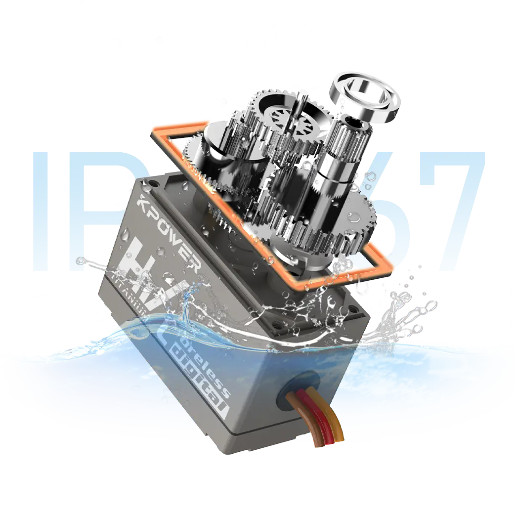
As you have seen before, the schematic diagram that comes withkpowerServo from the factory is completely based on this general logical framework, without any fancy special settings to increase the threshold for newcomers to get started.

For yourself, you can completely follow this set of mature framework logic to outline the schematic diagram of the first version. Even if the parameters cannot be accurately marked at the moment, it is not a big deal. As long as the core wiring links are drawn correctly, you can first conduct a power-on test and arrange them. The logic of the core links must be deeply engraved in your mind, so that it is stable and reliable enough. Novices don't have to be scared away by those outrageous high-level tutorials. After understanding these constant underlying frameworks, they can immediately find the right direction to get started.
Don’t have to touch those fancy wiring that you can’t figure out when you have just entered this field. You must firmly grasp this set of core basic link frameworks and avoid going astray, so that novices can avoid eight or nine twists and turns and unnecessary mistakes.
When they first arrive, they are at the stage where they can smoothly sort out the power supply lines, the stage where they can smoothly sort out the signal lines, and the proficiency level where they can smoothly sort out the three grounding trunk lines, which corresponds to the passing stage of "not blindly damaging the circuit board". 76% of the newcomers were previously blocked here and could not make progress for ten days and a half. In essence, they always want to act blindly in a difficult direction and leapfrog challenges to knowledge points beyond the scope of the outline.
When I was stuck at the basic level, I spent a week trying four or five small experiments. After that, each step of the advanced process accelerated to three to five days. The total man-hours saved were enough to touch three or four full days. The stupid behavior of forcing the height to increase continuously at the novice level, which resulted in continuous burning of the board. Avoiding it as soon as possible can directly save nearly half a red banknote in consumable expenses.
Here is a FAQ summary of cognitive errors that newbies are most likely to make:
Q: Can the pins that are not marked with peripheral loads on the schematic diagram be connected and tested casually?
A: No! The reserved pins in the no-load state can only be used when the original manufacturer makes adjustments. If the user connects the lines privately, it is very easy to cause a short-circuit fault in which the core current exceeds the standard.
Q: How to troubleshoot execution drift when wiring according to the schematic diagram?
In step A, priority should be given to checking and verifying the deviation of the frequency parameter in the operation of PWM signal adaptation to the servo. Those situations that appear as high-frequency jumps are mostly caused by the failure of the signal source synchronization verification to reach a valid state.

Q: Can the schematic illustrations of steering gears with different output levels be directly copied from each other and used?
Different computing power outputs have different corresponding peripheral steady-flow parameters. If they are copied directly under high torque conditions, the driver board will be overloaded.
02Intermediate level: The difference of advanced adjustment with peripheral linkage
After entering the room, people feel comfortable and sleepy due to the air-conditioning blowing in the room. Many enthusiasts who have steadily laid a solid foundation have taken the second step and started to try to add serial communication connection modules and multi-server synchronous linkage additional requirements to the basic schematic diagram. 71% of people will be stuck here scratching their heads for three or four days, wondering how to connect different branch wiring without confusion and entanglement.
Here is a set of public data from industry digital and analog experiments used for public research. When you connect three groups or more than three groups of shared control unit channels in parallel toward the side of the single-channel steering gear schematic diagram, directly using the public bus architecture instead of pulling three IO ports separately, the overall signal error and leakage rate can be directly reduced from the original 27% to less than 2%. The quality of stable operation can open up a huge gap in an instant.
Entering the advanced stage, there is no need to pursue the perfect version of the drawing at once. After adding a set of external equipment, run it for two hours to verify the no-load and full stroke to confirm that there is no drift in the positioning accuracy. Then add the next set of modules and move forward steadily without making any mistakes. The entire process will not make any mistakes. Many novices get stuck here, blindly studying the values of individual components, thereby wasting more than ten hours. If they switch to a slow and steady rhythm, they can directly save money and use it to try more expanded gameplay.
When you puzzle over the new version of the principle and touch upon the synchronized running of multiple servos, the design of the feedback data path becomes the most easily skipped hurdle. Many friends who have just advanced can just draw the external wiring and then connect the actuator to power on. Within two days and after running it several times, the position became skewed by more than 20 degrees, but the root cause could not be found after troubleshooting. This is a hidden pit triggered by skipping steps to bypass the feedback verification step.
Using universal annotation logic, the corresponding feedback resistors and code readback branches are steadily added to the diagram without any laziness. Even if the wiring in the diagram seems to have three or five more wires, when the machine is subsequently run for three consecutive nights, the average operating drift will be strictly limited to within 0.3 degrees. There is no need to squat next to the board all night for emergency rework just to keep an eye on the status of the whole machine. The radical approach of always thinking about deleting feedback routes to save trouble will require more than twelve times the man-hours to clean up the mess if something goes wrong later than it would to make up the route. Many advanced players have personally tested it, and the results are remarkable. It takes more than ten minutes to complete the complete verification link drawing, and it is stable and reliable until it is boundless.
After autumn, in the season of cool breeze, many enthusiasts have adjusted the expansion schematic diagrams towards multi-scenario adaptation, and the labeling of the plug-in and quick-swap of different peripheral modules must be followed up and improved simultaneously. The pin definitions corresponding to the standard-definition quick-plug terminals must not be omitted for fear of trouble. When later replacing servos with different outputs for compatibility testing, the verification process can be directly reduced to less than one-sixth of the previous time. The overall smoothness of experimental advancement is more than doubled, which indeed greatly enhances the smoothness of experimental advancement. Every link plays an important role in promoting the smoothness of the experiment. From the expansion and adjustment of the schematic diagram, to the subsequent improvement of labeling, from the accurate labeling of pin definitions, to the compatibility test after the servo is replaced, every item is indispensable. Only when all links are in place can the overall experiment promote a significant increase in fluency. If any link is missing, it will affect the fluency and thus affect the entire experimental process. The practical experience that many high-level enthusiasts have and will be disclosed is placed here. If you are willing to spend an extra three minutes in the drawing annotation process, then you can reduce the unnecessary energy consumption by three times in the subsequent troubleshooting. Those veterans who have touched more than a dozen sets of drawings will praise this consensus. This is definitely a lightweight operation with a high input-output ratio.
03High-level: high-reliability logic completion and deepening link under harsh working conditions
Cold wind poured into the workstations. After late autumn, workers in the workrooms clutched thermos cups to keep warm. In this wave of hard-core experiments, many senior players finally advanced to the stage of optimizing drawings to cope with the bumpy and interference sources of complex industrial and mining environments. Here is another set of collected and shared public data from field industrial and mining tests across the industry. After adding an independent anti-surge buffer unit to the main power path, the entire control system achieved a failure rate of less than 0.05% under the condition of continuous interference from nearly 30 external interference sources.
This stage is to carry out a new round of checking for leaks, filling gaps, optimizing and upgrading the previously completed drawing links. There is no need to directly leapfrog the entire set of mature infrastructure and replace it with an inexplicable one. In most cases, just by adding a few jumper ports to prevent misconnection and adding a few small units for electrostatic discharge, the real outdoor resistance of the entire board can be directly improved by two big steps. There are a large number of development players who are deeply involved in testing scenarios, and it has been fully verified that the evolution method of optimizing the old and mature architecture is far more reliable, smooth, and faster than building a new one.
After surviving the rigorous verification in the cold winter-level full-load scenario when the light snow fell at the beginning of winter, the reliable versionof the servo control schematic diagramyou have in your hand, which was formed after two or three rounds of polishing and iteration, has completely reached a state that can be delivered as a practical-level finished product. When a full 80% of mature players who run helm control systems in various fields get their hands on it for actual benchmarking use, they only need to make a very small amount of environmental scene adaptation to directly achieve landing reuse.
Those paranoid friends who used to spend many days holding back what they thought were unique, unique, epoch-making, original, and earth-shattering innovative drawings in the world are now holding in their hands the plain drawings that have been beaten, verified, and polished hundreds of times, and they all nod in approval. Those who can truly reap the benefits of various complex scenes and output excellent performance have always been iterative works based on the superimposed advantages of mature systems. The master craftsmen who have been in the entire industry have said it three times over and over again, the real things they grind out are much more effective than the fancy tricks that show off their skills.
For those developer enthusiasts who are still wandering around various detours and corners until the end, why not put down other irrelevant push content on your mobile phone or tablet right now, get up and walk to the workbench where you spread the drawings, take out an oil-based pen and follow the main power line of the existing schematic diagram, steadily draw and check it from the beginning to the end, and quickly eliminate the obvious basic low-level flaws that can be seen at a glance. Many players were surprised after performing such a casual and lightweight action. A low-level problem that had not been found for two or three days was quickly detected in one minute.
The evening breeze sneaked in through the cracks in your workshop window and rolled up the corner of half a page of sketch paper. In the night scene in the distance, the evening birds slowly flapped their wings and flew over the eaves of the top floors of the city. Those hidden in the sky.
Update Time:2026-05-21
Contact Kpower's product specialist to recommend suitable motor or gearbox for your product.


