


TECHNICAL SUPPORT


Published 2026-03-28
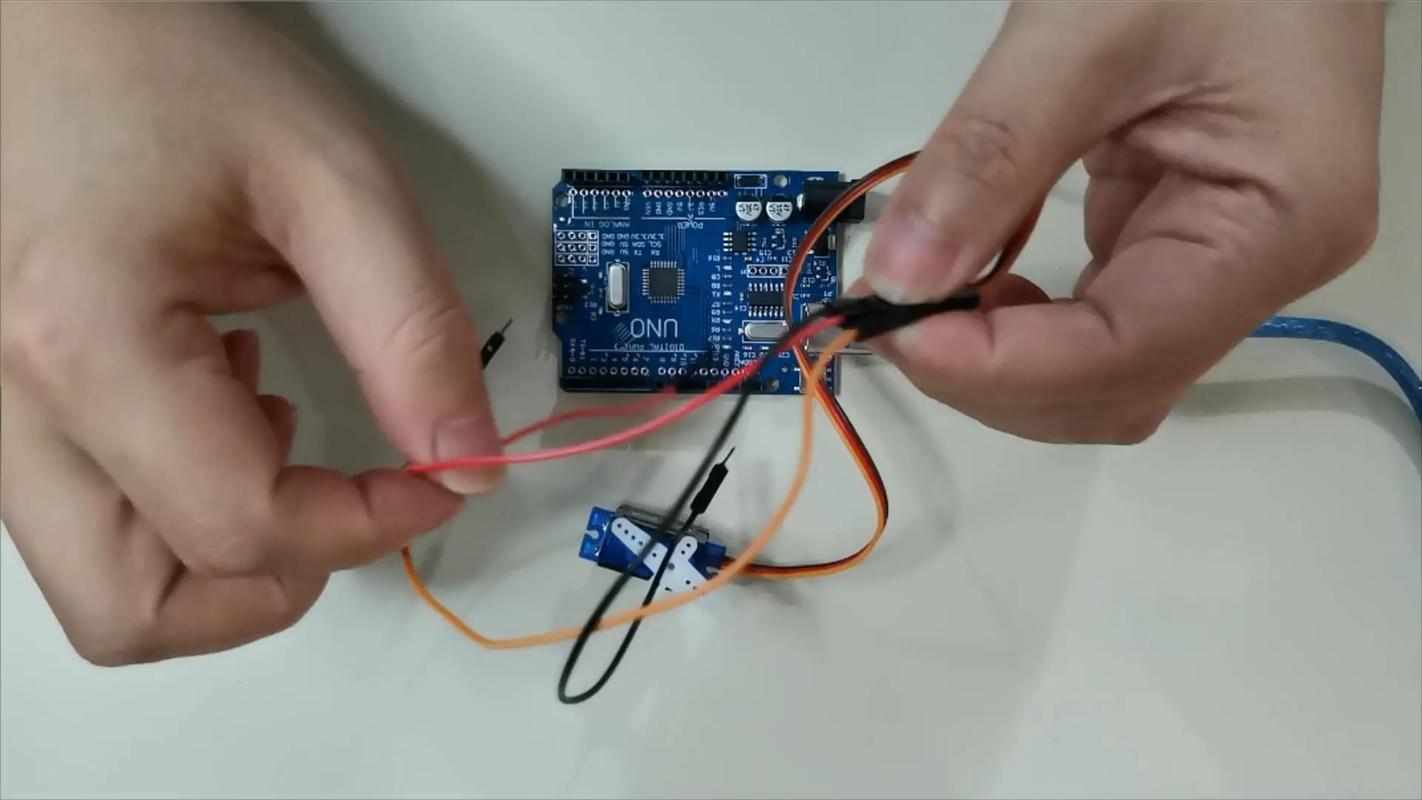
When engaged in product development, the biggest fear is not that the functions cannot be realized, but that the functions are stuck in the most basic wiring link. Obviously theservoseems to be quite simple. It only has three wires. Once plugged in, it either doesn't respond or emits smoke. Don't you think it's irritating? In fact, many times, it’s because I don’t understand that little interface diagram. Today we will specifically talk about theservointerface, so that you can look at the wiring diagram later and feel like a mirror.
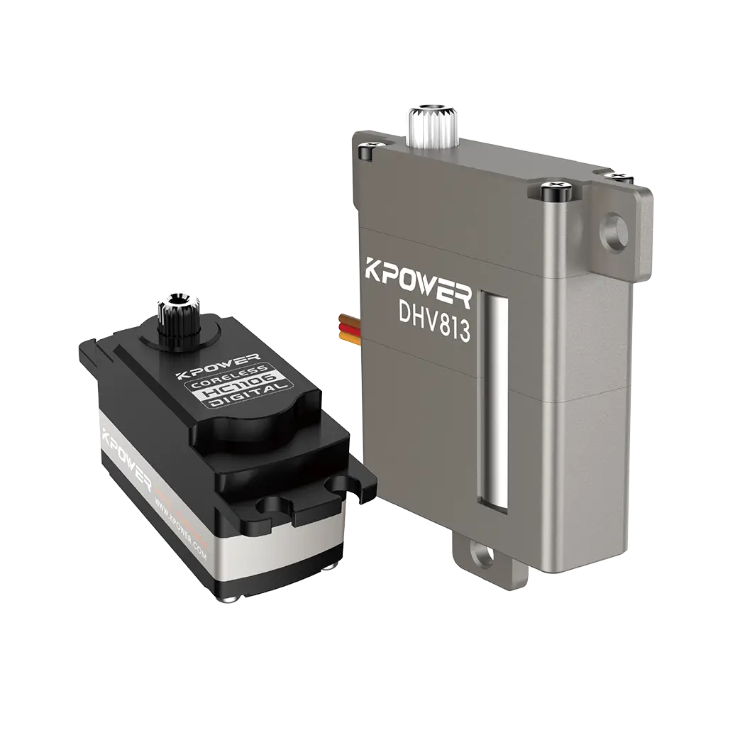
The three wires on the servo are different colors and have completely different divisions of labor. Usually the red one is the positive pole of the power supply, which is connected to 5V or 6V voltage, depending on the model of the servo; the brown or black one is the negative pole of the power supply, which is the ground wire; the orange or yellow one is the signal line, which is specially used to receive control instructions. You can think of these three wires as a takeout order. The power wire is for charging the rider's battery car, and the signal wire is the order notification on the phone. Without anyone, the job can't be done.
A common mistake that many novices make is confusing the power cable and the signal cable. For example, if the signal line is connected to the power supply, the servo will keep spinning randomly or not work at all; conversely, if the power supply is connected to the signal pin, it will be even worse, directly burning out the driver chip inside. Therefore, take ten seconds to confirm the color correspondence before wiring. This can help you save a lot of rework time and material costs.
The wiring sequence of different brands of servos is not necessarily the same. There are two common ones: one is the positive electrode in the middle, and the signal and ground wires are on both sides; the other is the positive electrode is on the side. The safest way is to directly check whether there is a mark printed on the servo housing. Usually there will be a small picture on the top or side of the servo with "S", "+" and "-" drawn on it, which represent the signal, positive pole and negative pole respectively. If you really can’t find the logo, take out the product manual or search online for the specific model number.
If you use several servos of different brands at the same time, it is recommended to develop a good habit: every time you get a new servo, take a photo of the interface logo and save it. This trick is particularly effective. When debugging a multi-axis robot or robotic arm, there are dozens or twenty servos lined up together. You can quickly confirm the connection method of each one by looking at the photos, and you no longer have to rummage through the box to find the instruction manual.
The signal line must be connected to the pin on the main control board that supports PWM output, such as pin 9, pin 10, or the STM32 timer channel. The PWM signal tells the servo to which angle it should turn through changes in pulse width. You can think of it as you are shouting to the servo, "Turn right 10 degrees" or "Turn left 20 degrees", but in the form of electrical signals instead of sounds.
The pitfall that many people easily fall into at this step is that they randomly plug the signal line into an ordinary IO port, only to find that the servo either keeps shaking or doesn't respond at all. Because the ordinary digital port outputs high and low levels, it cannot simulate the continuous pulse changes like PWM. Therefore, before wiring, be sure to confirm which PWM pins are on the main control board. Don't wait until the program is burned in to find out that they are connected in the wrong position.
The interface diagram provided by the manufacturer is actually not that complicated. The key is to capture a few core elements. The pin number, corresponding signal definition, and recommended power supply voltage are generally marked on the diagram. Some people will also draw an outline of the servo and draw three lines on the side, marking the color and function respectively. When you look at the picture, focus on the correspondence between the colors and pin positions, rather than just looking at the order of the lines.
For example, some manufacturers will put the signal line on the far left, and some will put it on the far right. If you only look at the appearance of "three lines side by side" and don't read the labels on the picture carefully, it is easy to connect them the wrong way. Another situation is that the picture will indicate "only supports 3.3V signals" or "compatible with 5V logic". This is particularly important, especially when you use a 3.3V main control board to drive a servo with a 5V signal, you may need to add a logic level conversion module, otherwise the servo may work unstable.
The consequences of connecting the wrong wires may range from the servo not responding to the worst case to smoking and being scrapped. The two most common situations of burning the servo are: one is that the positive and negative poles are connected reversely, and the current flows directly back, burning the internal control chip; the other is that high voltage is connected to the signal pin, such as directly connecting 12V to the signal line, which is basically hopeless. Sometimes, although the servo does not burn, the servo will vibrate, not return to zero, become severely heated, and other abnormal phenomena.
Once these situations occur, not only will you have to spend money to buy another servo, but what's even more troublesome is that it will delay the development progress. The action that could have been adjusted today may have to wait two or three days for express delivery due to a wiring problem. Therefore, it is very important to develop the habit of "confirm again" before powering on. Especially when connecting key equipment, it is safest to use a multimeter to test the continuity first to confirm that there is no short circuit, and then power on and test.
After connecting the lines, the easiest way to verify is to write a simple test program. Let the servo turn to 0 degrees first, wait two seconds, and then turn to 180 degrees, and execute the cycle. If the servo rotates smoothly back and forth, the wiring is OK. If there is random rotation, lag or no rotation, you can check from three aspects: whether the power supply voltage is sufficient, whether the PWM pin connected to the signal line is correct, and whether the angle range setting in the program is reasonable.
️ Here’s a little tip: when you first start debugging, don’t install the servo directly on your mechanical structure, test it by hanging it in the air first. In this way, even if the wiring is wrong, the structural parts will not be damaged. Wait until you confirm that the wiring and procedures are normal before fixing the installation. In addition, if multiple servos are used in your project, it is recommended to connect them one by one for testing instead of plugging in all the wires at once. This will make it easier to locate which servo is responsible for a problem.
When debugging the servo, have you ever encountered any particularly puzzling wiring problems? Welcome to share it in the comment area so that other friends can avoid detours. If you think today's content is helpful to you, please give it a like and support. I will continue to share more practical information in product development.
Update Time:2026-03-28
Contact Kpower's product specialist to recommend suitable motor or gearbox for your product.


