


TECHNICAL SUPPORT


Published 2026-03-28
When playing with aservo, the most troublesome thing is that it suddenly "goes on strike" or shakes violently. In many cases, it's not because theservois broken, but because you don't understand how much current it draws. If this calculation is not accurate and the power supply cannot keep up, the rudder may not be able to move, or the control board may be directly burned. Today I will break it apart and crush it to discuss this key issue.
How much is the locked rotor current?
We must first understand the most extreme situation, which is stalled current. So what is stalling? To put it simply, it means that theservois stuck when it reaches the end, or it is the moment when the maximum power needs to be exploded. The current in this situation is extremely amazing. After actual measurement, at a voltage of 6V, the locked-rotor current can easily soar to 2.5A or even higher, and it is not surprising that the instantaneous peak value reaches 3A. Many friends directly use mobile phone power bank or USB port to provide power. However, the output of several hundred milliamps cannot bear it at all. The protection will be triggered in an instant and the power will be cut off. In the end, they mistakenly think that the servo is broken. So be sure to remember that this current is not normal, but you must configure the power supply according to this upper limit.
In addition, we also need to consider some other factors during the actual use of the steering gear. For example, although the current consumption of the servo during normal operation is not as large as the locked-rotor current, if it works continuously for a long time, the accumulated power demand cannot be underestimated. Moreover, the current consumption of the servo will also change under different working modes and load conditions. Therefore, when selecting a power supply for the servo, you must not only refer to the upper limit of the locked-rotor current, but also comprehensively consider various possible situations to ensure that the power supply can stably and continuously provide sufficient power support for the servo to ensure that the servo can operate normally and efficiently.
Normal operating current range
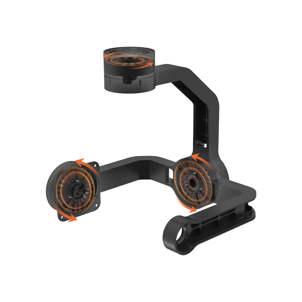
So what is the normal rotation speed? This depends on the load you carry. When no-load, the operating current is actually quite gentle, only about 200 to 300 mA, so there is no pressure when moving. But as long as you connect a wheel, a robotic arm or a heavy structure, the current will rise immediately, usually jumping back and forth between 0.5A and 1A. For example, if you make a simple servo gimbal and follow the rotation of the object, the current will basically be within this range. If you feel that its movements are a bit sluggish or its sound is muffled, it's probably because the current is tight and the voltage has been pulled down. You need to quickly check to see if the power supply can't keep up.
How to calculate power supply
After knowing the current-related information, we can calculate the power supply, and this is the key to avoiding falling into the pit. Suppose you use 4 at the same time to make a quadruped robot, and each is calculated according to the maximum 1.5A (never calculate according to no load, it is completely deceiving yourself). In this way, the total current will go towards 6A. In this case, if you configure a 5V 3A power supply, it will definitely not be enough. According to the power formula P=UI, the result of multiplying 6A by 5V is 30 watts, so you must find a power supply with an output of at least 30 watts. By the way, many players are keen on using 18650 battery packs. Remember to calculate the discharge rate at this time. If the continuous discharge of a single battery is only 5A, do not use it forcefully if it cannot be carried.
In addition, when calculating the power supply, the current data must be accurately grasped. As mentioned before, if 4 are used to make a quadruped robot, each one is calculated at a maximum of 1.5A, and the total current is 6A. This is a very important premise. After calculating the required power according to the power formula, it is crucial to choose the appropriate power supply. For players who like to use 18650 battery packs, the calculation of discharge rate cannot be ignored. If a single battery is continuously discharged and only has 5A, don't force it on if it can't be carried, otherwise it may cause a series of problems and affect the normal operation of the entire device.
Difference in current at different voltages
Voltage also has a particularly large impact on current, which is a detail that many people ignore. It can work from 4.8V to 7.2V, but if you give it 6V and 7.4V, the current performance is completely different. The higher the voltage, the stronger the steering gear will be, and the locked-rotor current will also increase accordingly. For example, if it is stalled at 2.5A at 6V, and you drive it to 7.4V, it may go directly to 3.2A. So when you choose a lithium battery, the 2S battery is fully charged at 8.4V, which is only a little higher. The power module and circuit must be upgraded accordingly, otherwise the heat will be serious and the wires will be scalded even if they are thin.
Typical symptoms of insufficient power supply
In fact, there are signs of insufficient power supply. You don’t have to wait until the servo is completely motionless to find out. The most common symptom is "rudder shaking", that is, when the servo is stopped at a certain position, it will shake at a high frequency like Parkinson's disease. This is caused by the voltage being pulled down and the control signal being unstable. Also, if you ask it to rotate 90 degrees in your program, it turns out to be slow as if it has not eaten enough, and it will bounce back a little when it is halfway turned. This is a typical symptom of insufficient current feeding. The most serious thing is to restart directly with a black screen. Once the control board loses power, the entire project will be wasted, and the chip may be burned out after a few more attempts.
How to choose power supply and cables
Finally, let’s talk about something practical, how to reliably distribute the power supply and wires. In terms of power supply, it is strongly recommended to use a combination of voltage stabilizing module and battery. For example, an adjustable step-down module is equipped with a 2S lithium battery. The voltage is stable at 6V. It is best to choose a module with a current output of more than 5A. It is always good to leave some margin. Wires are also critical. Don’t use thin DuPont wires to handle large currents. The voltage drop will make you doubt your life. Directly connect 20AWG or thicker silicone wire, and change the connector to XT30 or directly weld it, so that the current can flow smoothly into the servo.
Have you ever encountered an embarrassing situation where the project overturned because the current was not calculated accurately? Welcome to share your pitfall experience in the comment area. Let’s avoid lightning together. If you find it useful, don’t forget to like and save it so that more friends who play with servos can avoid detours.
Update Time:2026-03-28
Contact Kpower's product specialist to recommend suitable motor or gearbox for your product.


