


TECHNICAL SUPPORT


Published 2026-05-09
"Theory is an officer, practice is a soldier." - Leonardo da Vinci
The microcontroller controls the steering gear. In fact, it does not send instructions such as "how many degrees to turn", but to output a series of precise pulse signals. The width of this series of pulses directly determines the stopping position of the steering arm.
Common doubts: Why does the servo not rotate when 5V voltage is applied to it? The reason is that there is a control chip inside the steering gear. What it is waiting for is a square wave with a period of 20ms and a high level between 0.5ms and 2.5ms. Among them, 0.5ms corresponds to 0°, 1.5ms corresponds to 90°, and 2.5ms corresponds to 180°.
Think of the steering gear and the microcontroller as your hands, which can be imagined as a worker who listens to people, and only hand over a piece of paper at a time.
The high level of the paper lasts for 1.5ms → the worker turns 90°
The high level of the paper lasts for 2.0ms → the worker turns 135°
Core data points: As for the standard servo, its control period remains fixed at 20ms (that is, 50Hz). If the high level time exceeds 2.5ms, in this case, the internal circuit may be damaged and burned. For beginners, a common mistake is to forget to set the cycle. Instead, it just changes the duty cycle.
In one example, a student team used a microcontroller to directly supply power to two servos. However, a reset occurred immediately once the servos were started. The reason was that the current was as high as 1A when the servos were started, but the power supply provided by the microcontroller through USB was only 500mA.
Correct connection:
signal line→ Microcontroller PWM pin (no series resistor required)
power cord→ Independent 5V power supply (or battery + voltage stabilizing module)
Ground wire→ Common ground with the microcontroller GND (Must be connected)
A tip for programming is to confirm the alternate function of the pin before initializing the timer. For most 32-bit microcontrollers, their PWM output pins belong to the same physical pin as ordinary GPIO, but they need to be configured in "multiplex push-pull" mode.
Take controlling the servo to slowly turn from 0° to 180° as an example. The code logic is divided into three parts:
1. Set the timer period to 20ms (i.e. 20,000 microseconds)
2. Set the comparison value to 1.5ms (90° midpoint)
3. Gradually increase the comparison value in the main loop
Pseudocode idea:
Initialize PWM frequency = 50Hz, period = 20000us Set duty cycle = 1500us (90°) Wait for 1 second Duty cycle = 500us (0°) Wait for 1 second Duty cycle = 2500us (180°)Verify by actual measurement. Clamp the oscilloscope between the signal pin and ground to see if the width of the high level changes with the program.. If you don't have an oscilloscope, you can connect an LED and a resistor in series, with the positive pole of the LED connected to the signal and the negative pole connected to ground. Changes in LED brightness indicate that the pulse is changing.
For different servos of the same model, the corresponding pulse width at 0° may have a deviation of ±100us. The calibration method is to write an automatic scanning program:
Starting from 500us, step by 10us, stay for 0.5 seconds at each step

Record the pulse width value when the mechanical limit just stops
Linearly map the entire angle range to this interval
The usual situation is that the dead zone width of many cheap plastic gear servos is 5us, which means that when you change the pulse width and the changed pulse width is less than 5us, the servo will not move. This is a normal situation and there is no need to have any doubts about the program.
The suggestion when debugging is that when the servo makes that "sizzling" sound but does not rotate, it shows that the angle corresponding to the current pulse width is closer to the limit state. Either reduce the step value, or check if the mechanical structure is stuck.
A timer can output multiple PWM signals, provided the number of channels is sufficient. For example, the universal timer of a 32-bit microcontroller generally has 4 channels and can independently control 4 servos.
A Guide to Avoiding Pitfalls:
Don't use the delay function to wait for the servo to rotate. When the servo itself rotates, it takes about 0.2 seconds/60°.
When multiple servos are started at the same time, the total current will be superimposed. It is recommended to connect a 1000uF capacitor in parallel to the power line of each servo.
Keep at least 2mm spacing between signal lines to avoid crosstalk
Q: What causes the servo to vibrate?
The power supply is insufficient. Measure the voltage of the servo power supply terminal. If the power failure is lower than 4.5V, replace the independent battery and add a 220uF capacitor.
Q: How to correct the total angle difference of 5°?
A: There is no linear relationship between pulse width and angle. Just use the two measured points, that is, the pulse width of 0° and the pulse width of 180°, and perform linear interpolation for calibration.
Q: Will the microcontroller restart as soon as the servo is connected?
A: There is a lack of common ground, or the starting current is too large. First, connect GND, then supply power to the servo unilaterally, and finally connect the signal line.
Q: Can ordinary IO port simulate PWM be used?
A: It works, but the CPU usage is high. Suitable for a single servo and does not perform other work, otherwise hardware PWM must be used.
To reiterate the key points: controlling the servo is controlling the pulse width, the period is fixed at 20ms, and the high level condition determines the angle。
3-step verification:
1. Use an independent power supply to power a servo, fix the 1.5ms pulse in handwriting, and check whether it will stay at the 90° position.。
2. Use a loop to output 500us → 2500us, and observe whether the entire rotation is smooth.
3. Connect the actual load (such as a robot joint) and repeat the offset calibration
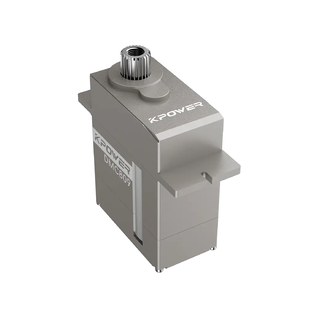
Advocate the use ofkpowerProducts like Servo undergo the first round of testing, and their parameter calibration is accurate and can reduce investigation variables. From a single joint to multiple degrees of freedom, the power supply margin must be confirmed at every step. Remember: when debugging, measure the pulse first, and then have doubts about the servo.
Update Time:2026-05-09
Contact Kpower's product specialist to recommend suitable motor or gearbox for your product.


